Overview
The digitalWrite() statement here is used to write high level or low level to pins and to let LED and active buzzer 「work 」or 「stop」. In this lesson, we will take LED as an example to introduce the experiment phenomenon.
Components Required
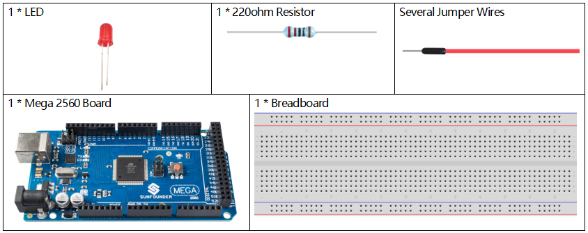
Note: Refer to Part 2 to check details of hardware.
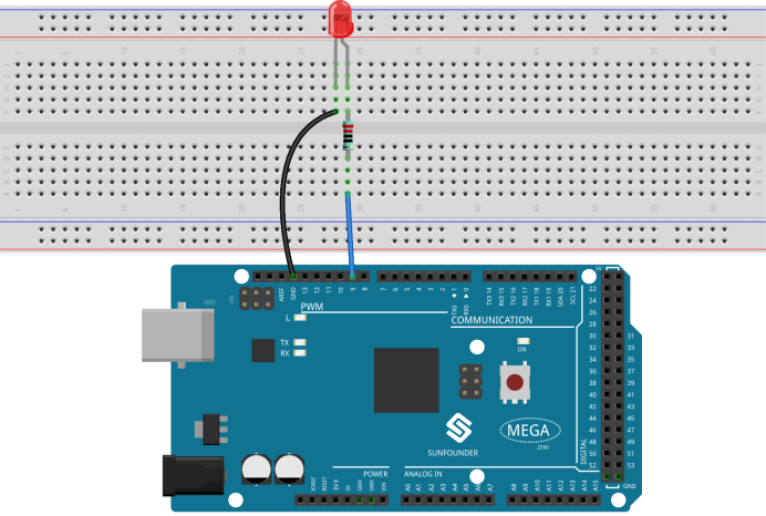
Fritzing Circuit
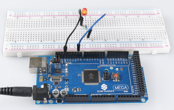
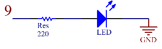
In this example, we use digital pin 9 to drive the LED. Attach one side of the resistor to the digital pin 9 and the longer pin (anode) of the LED to the other side of the resistor. Connect the shorter pin (cathode) of the LED to GND.
Schematic Diagram
Code
After finishing the circuit connection, connect the Mega2560 board to the computer. Run the Arduino software IDE and type in the following codes.
NOTE: You can also open the 1.2digitalWrite.ino file in the path of sunfounder_vincent_kit_for_arduino\code\1.2digitalWrite to use the codes.
const int ledPin = 9;
void setup()
{
  pinMode(ledPin, OUTPUT);
}
void loop()
{
  digitalWrite(ledPin, HIGH);
  delay(1000);
  digitalWrite(ledPin,LOW);
  delay(1000);
}
Upload the codes to the Mega2560 board, and you can see the blinking of LED.
Code Analysis
Here, we connect the LED to the digital pin 9, so we need to declare an int variable called ledpin at the beginning of the program and assign a value of 9.
const int ledPin = 9;Now, initialize the pin in the setup() function, where you need to initialize the pin to OUTPUT mode.
pinMode(ledPin, OUTPUT);In loop(), digitalWrite() is used to provide 5V high level signal for ledpin, which will cause voltage difference between LED pins and light LED up.
digitalWrite(ledPin, HIGH);If the level signal is changed to LOW, the ledPin’s signal will be returned to 0 V to turn LED off.
digitalWrite(ledPin, LOW);An interval between on and off is required to allow people to see the change, so we use a delay(1000) code to let the controller do nothing for 1000 ms.
delay(1000);※ How to Upload the Sketch
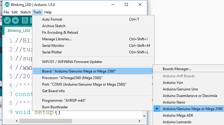
Before you upload a written code to Arduino, you need first to select Board and Port.
Click Tools ->Board and select Arduino/Genuino Mega or Mega 2560.
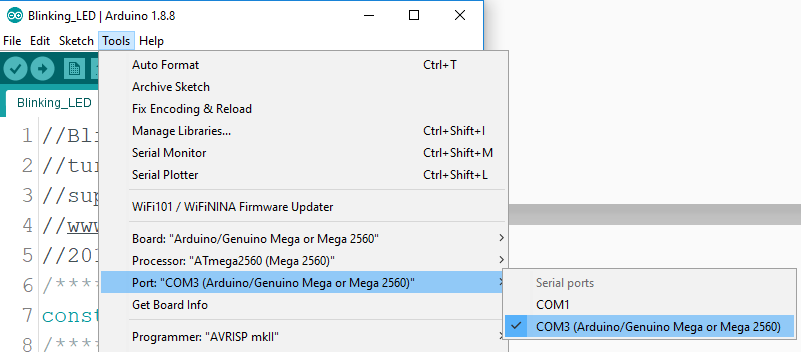
Then select Tools ->Port. Your port should be different from mine.
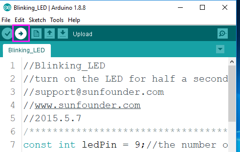
Step 4: Upload the sketch to the SunFounder Mega2560 board. Click the Upload icon to upload the code to the control board.
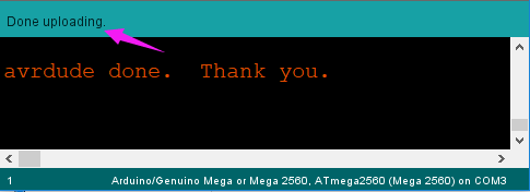
If “Done uploading” appears at the bottom of the window, it means the sketch has been successfully uploaded.
Phenomenon Picture