Overview
With the understanding of digitalWrite() and digitalRead(), we can build a complete I / O system to control the output device by obtaining the data from the input device. We can use this method to enable digital input components such as Button, Touch sensor, Infrared motion sensor to control digital output devices such as LED, active buzzer. This lesson will take Button and LED as examples to realize button control LED with the condition (if-else).
Components Required
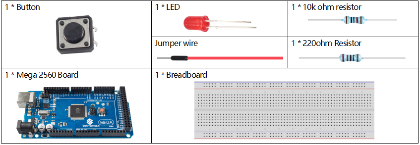
Note: Refer to Part 2 to check details of hardware.
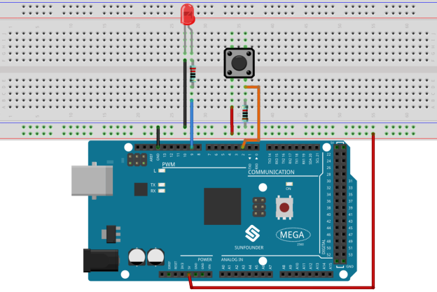
Fritzing Circuit
In this example, we use pin 9 to drive LED. Use digital pin 2 to read the signal of Button. When the button is pressed, the LED lights up.
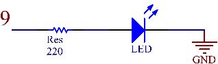
Schematic Diagram
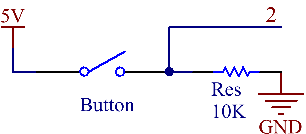
Code
const int buttonPin = 2;
const int ledPin =  9;
int buttonState = 0;

void setup()
{
  pinMode(ledPin, OUTPUT);
  pinMode(buttonPin, INPUT);
}

void loop()
{
  buttonState = digitalRead(buttonPin);
  if (buttonState == HIGH)
  {
    digitalWrite(ledPin, HIGH);
  }
  else
  {
    digitalWrite(ledPin, LOW);
  }
}
After uploading the code to the Mega2560 board, you can hold down Button to lighten the LED.
Code Analysis
Declare the pins of LED and Button and declare a variable to store the state of button.
const int buttonPin = 2;
const int ledPin =  9;
int buttonState = 0;
Initialize the pin mode in setup().
pinMode(ledPin, OUTPUT);
pinMode(buttonPin, INPUT);
Read the status of the Button in loop() and assign it to the variable buttonState.
buttonState = digitalRead(buttonPin);Use if condition to judge: if you get high level from a button, light up the LED.
if (buttonState == HIGH)
{
    digitalWrite(ledPin, HIGH);
}
Otherwise, turn off the LED.
else
{
digitalWrite(ledPin, LOW);
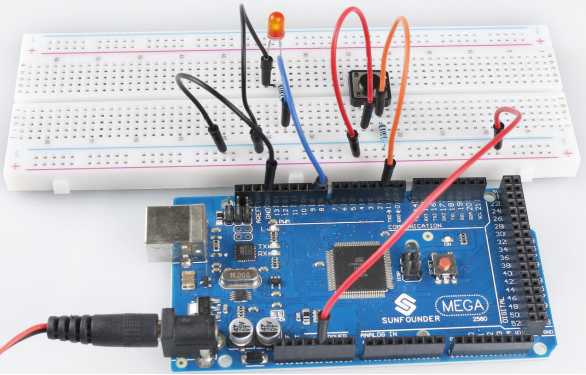
}Phenomenon Picture