An Arduino board is doubtlessly necessary. There are many types of the Arduino board to meet various requirements. The normally-used ones include Arduino Uno, Nano, Mega2560 and Leonardo. Some others such as Arduino Ethernet and Yun, etc., are with extension functions. You can detailed information of these boards on the official website of Arduino and thus choose the right boards according to your own needs.
There’s a gorgeous board in the kit. It’s exactly the Arduino-compatible SunFounder Mars/Mercury board named after the planets. More SunFounder boards will be named after other planets in the future, possibly making a series of typical boards. Follow our website for news!

The Mars and the Mercury board is a version optimized based on the Arduino Uno and Mega2560 board respectively. You can tell the difference from their more splendid color. Their basic functions are pretty similar but ours are easier to operate. Now, let’s see the details.
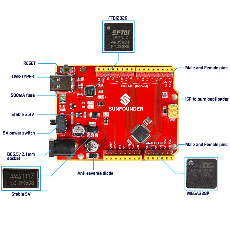
2.1.1 SunFounder Mars Board
SunFounder Mars board is totally compatible with the official Arduino Uno board, with also ATmega328P as the processor, and the same Optiboot bootloader as Uno does. And it has 14 digital I/O pins and 6 analog inputs and is featured with a 32KB program storage and 16MHz crystal oscillator and so on.
Multiple features make it unique: beautiful red PCB, parallel yellow and red pins, and a beautiful red appearance. In technology, it uses FTDI232R for USB-to-serial and adopts Type-C, the only USB port so far that supports reversible plug orientation. All the I/O ports are made with two pins (male and female) in a row, for free to use – you can just plug Dupont wires regardless of M or F.
A 5V power switch is added to control the board power, which may be expected by mass hobbyists – you can switch off the board when it’s not in use, so as to avoid frequent plugging. In addition, a reset button is set at the board side for convenience. To save space, the ATmega328P microcontroller is packaged in patch.
The figure below shows its characteristics:
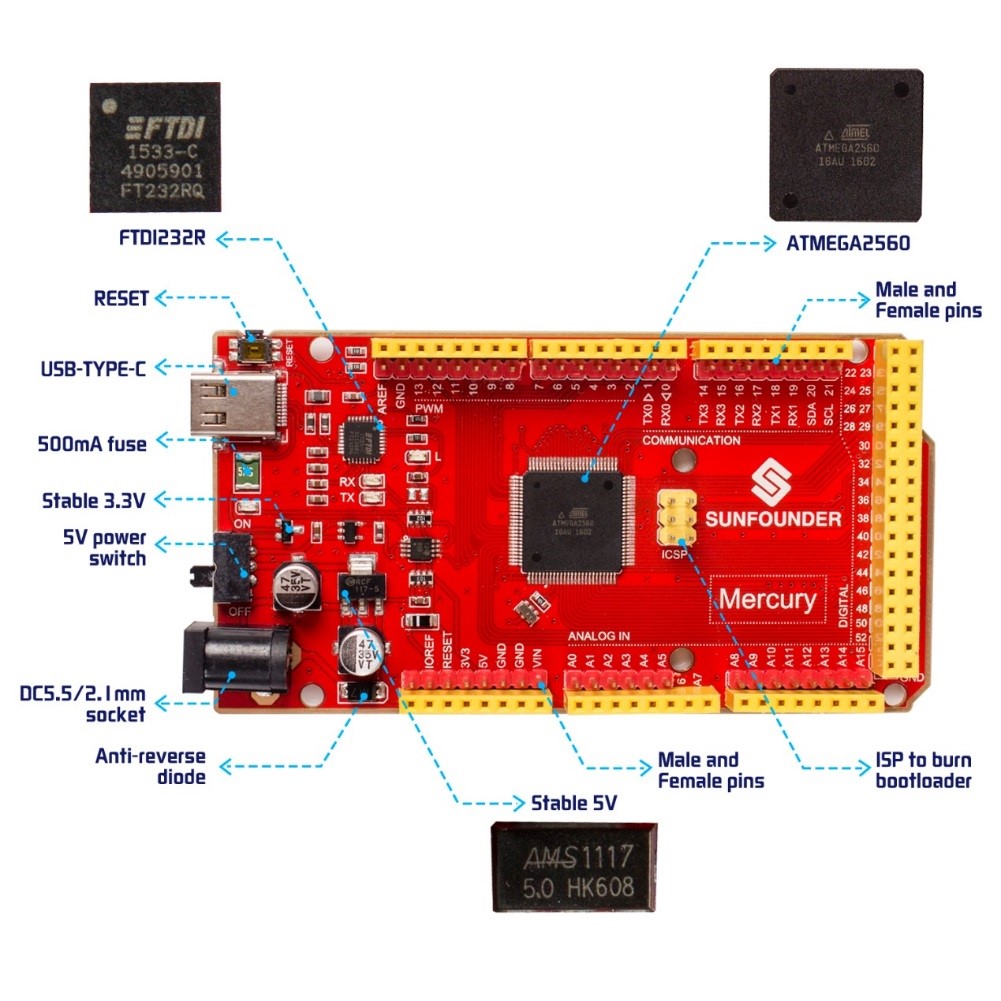
2.1.2 SunFounder Mercury Board
The Mercury board is totally compatible with the official Arduino Mega2560 board, most of whose features are the same with the Mars board except that the Mercury board runs the ATmega2560 as the processor. Therefore, it has more digital I/O (54 pins) and analog input pins (16 pins), a larger flash program storage (256KB), and 4 hardware serial ports. With all these features, the Mercury board can be applied in some bigger projects that need multiple hardware serial ports.
Check the details in the following figure.
2.1.3 USB Type-C Cable
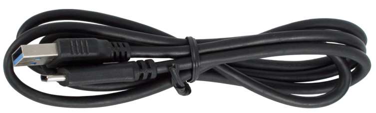
A USB cable is needed for the communication between the Arduino and the computer, for data transmission. The Arduino board can also get power via this USB cable. In addition, a type-C plug is used, making it easy to operate because you can just plug it in and do not need to worry about plugging it upside down.
2.1.4 Breadboard
A breadboard is a construction base for prototyping of electronics. It is used to build and test circuits quickly before finalizing any circuit design. And it has many holes into which components like ICs and resistors as well as jumper wires mentioned above can be inserted. The breadboard allows you to easily plug in and remove components. So if there are going to be many changes or if you just want to make a circuit quickly, it will be much quicker than soldering up your circuit. Therefore in lots of experiments, it is often used as a hub to connect two or more devices.
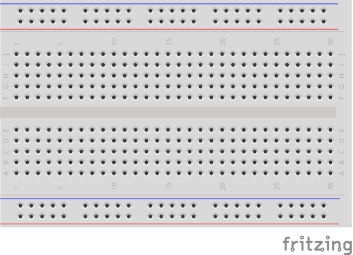
Normally, there are two types of breadboard: full+ and half+. You can tell their difference from the names. A half+ breadboard is half the size of a full+ one and their functions are the same. Here take the full+ breadboard.
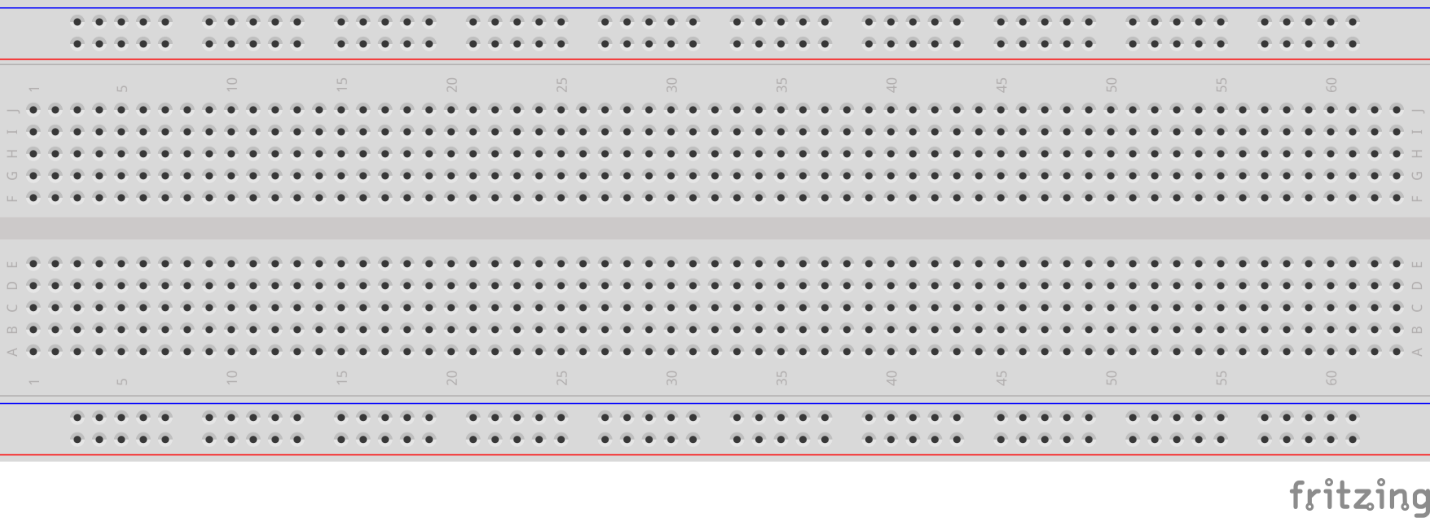
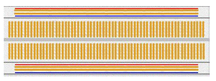
This is the internal structure of a full+ breadboard. Although there are holes on the breadboard, internally some of them are connected with metal strips. Those holes are to insert pins of devices or wires. There are four long metal strips on the long sides; the blue and red lines are marked just for clear observation. But you can take the blue line as the GND and red one as VCC for convenience. Every five holes in the middle are vertically connected with metal trips internally which don’t connect with each other. You can connect them horizontally with wires or components. A groove is made in the middle for IC chips.
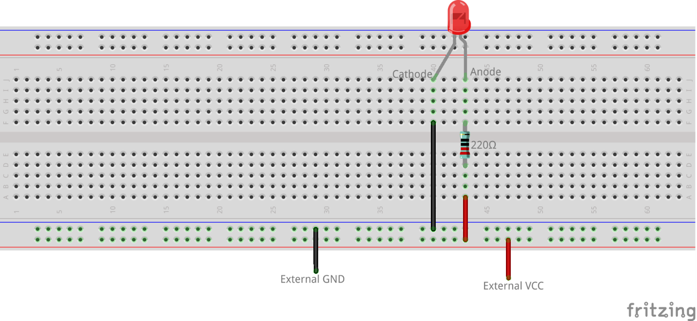
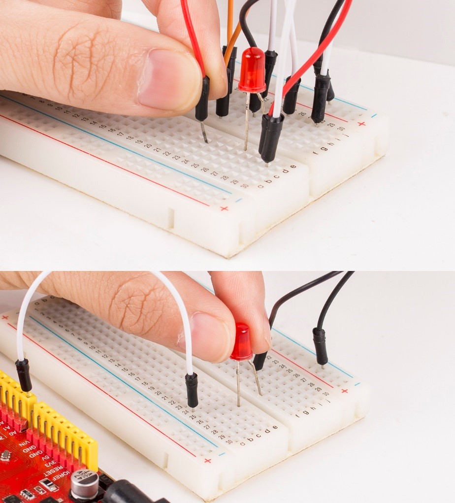
Now let’s make some simple experiment with the breadboard. Turn on an LED as shown in the figure below. You can have a try and the LED will light up. The breadboard makes it possible for you to plug and pull components at any time without welding, which is very convenient for tests.
2.1.5 Jumper Wires (Male-to-Male)
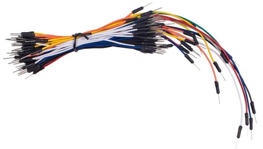
Wires that connect two terminals are called jumper wires. There are various kinds of jumper wires. Here we focus on those used in breadboard. Among others, they are used to transfer electrical signals from anywhere on the breadboard to the input/output pins of a microcontroller.
Jumper wires are fitted by inserting their “end connectors” into the slots provided in the breadboard, beneath whose surface there are a few sets of parallel plates that connect the slots in groups of rows or columns depending on the area. The “end connectors” are inserted into the breadboard, without soldering, in the particular slots that need to be connected in the specific prototype.
There are three types of jumper wire: Female-to-Female, Male-to-Male, and Male-to-Female. The reason we call it Male-to-Female is because it has the outstanding tip at one end as well as a sunk female end. The Male-to-Male jumper wires are included in the kit which you can insert into the breadboard or control board. The color of the jump wires is different but it doesn’t mean their function is different accordingly; it’s just designed so to better identify the connection between each circuit, and also make the whole circuit colorful and more good looking.
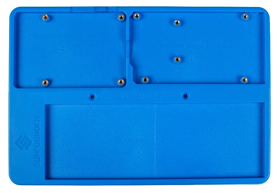
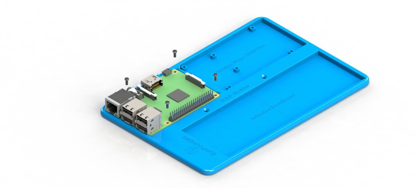
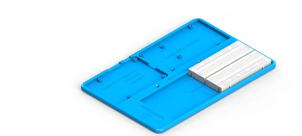
2.1.6 SunFounder RAB Holder
The Sunfounder RAB Holder is a board in the learning kit used for fixing a breadboard, an Arduino board and/or a Raspberry Pi board. It is quite easy to use.
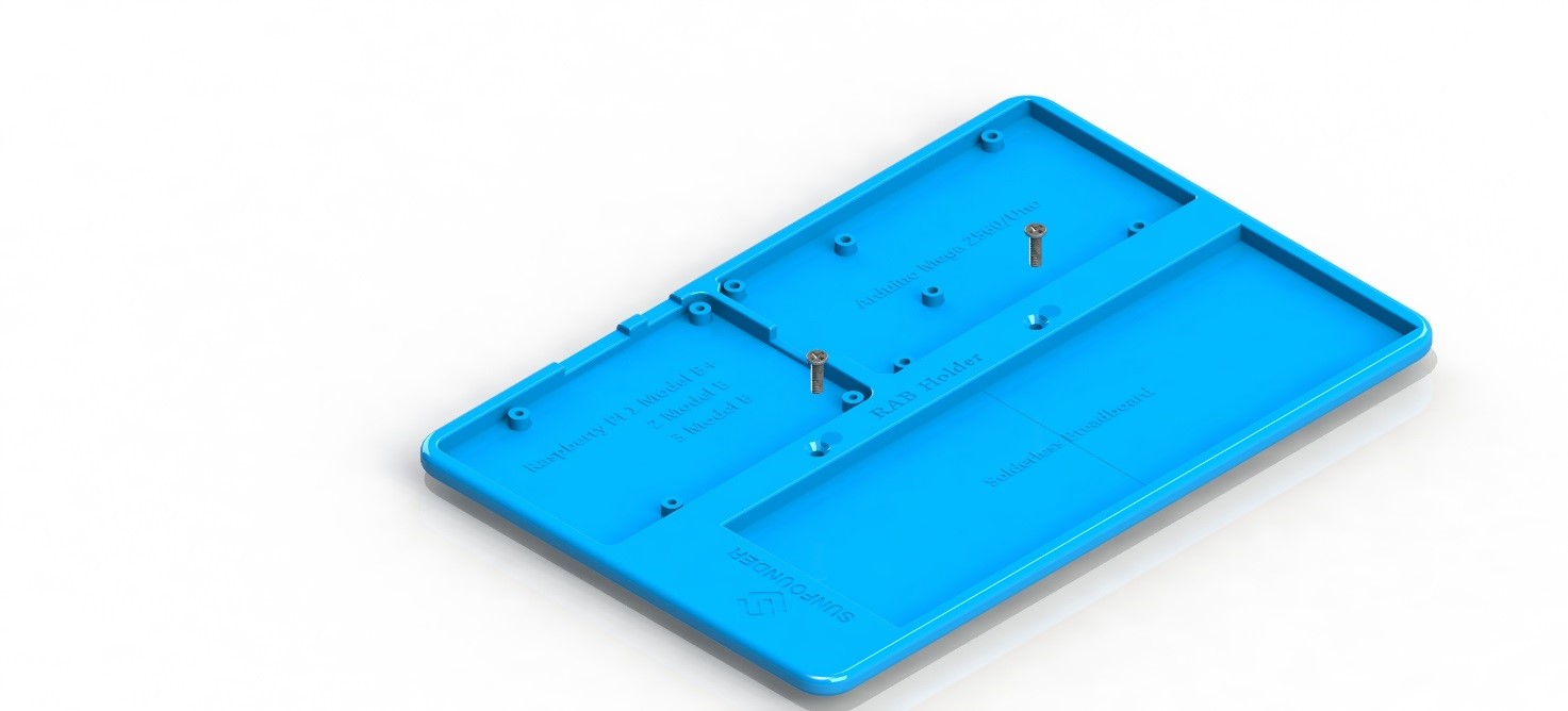
If there are two M3*3 (or deeper) threaded holes with a center distance of 70mm on the testbed, just insert the M3*10 flat screws through the holes on the RAB holder and into those on the testbed and tighten them up. You are not recommended to fix the holder if there’s no holes to fix in case of damaging the testbed.
The RAB holder consists of three fixed areas, each one suitable for fixing a series of boards.
The top left area as the No. 1 area: fit for the Raspberry Pi 1 Model B/B+, 2 Model B and 3 Model B.
Installation: There are four fixed nuts in the mounting holes. Insert 4 M2.5*6 screws into holes of a Raspberry Pi board and the nuts to fix the board.
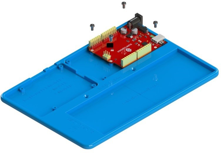
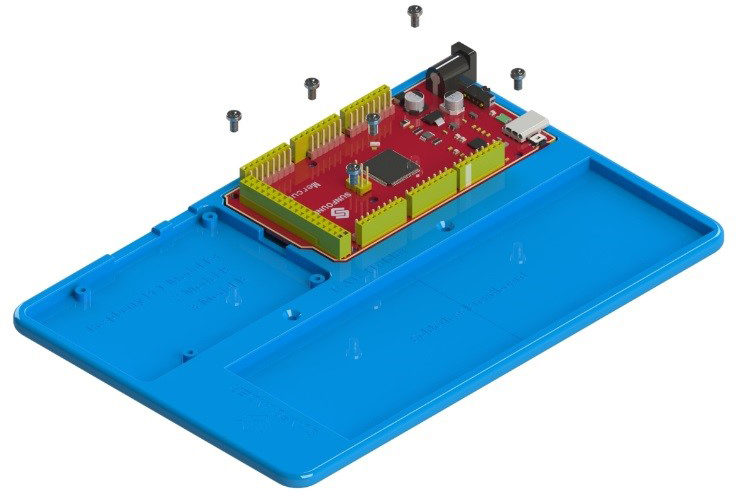
The top right corner as the No. 2 area: for the Mercury (Mega 2560) or the Mars (Uno) board.
Installation: There are six mounting holes with six fixing nuts. Insert 6 M3*6 screws into the 6 nuts and tighten them up to fix the Mercury board (DO NOT tighten too hard so the USB cable can be plugged in). For the Mars board, insert four screws into four nuts and tighten them as shown in the figure below. The two boards cannot be installed simultaneously.
The bottom as the No. 3 area: to fix a breadboard (a full or half).
Installation: To fix the breadboard, remove the sticker at its back and stick it firmly to the area.
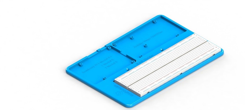
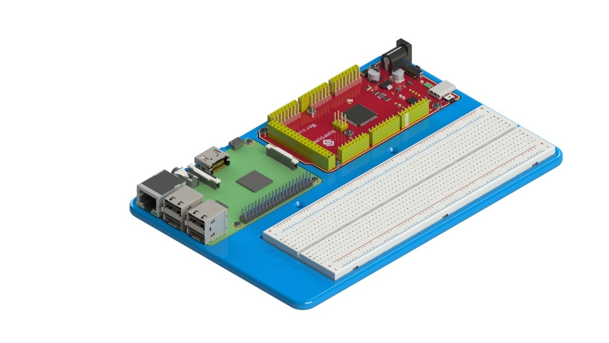
You can use the three areas based on actual needs: the components and parts provided and needed in the learning kit. Although each area is applicable for several boards, only one board is allowed to be fixed in each area at one time.
Take the following application:
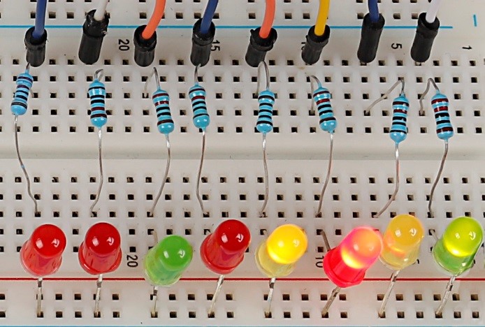
2.1.7 Resistor
Resistor is an electronic element that can limit the branch current. A fixed resistor is one whose resistance cannot be changed, when that of a potentiometer or variable resistor can be adjusted.
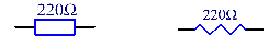
The resistors in this kit are fixed ones. It is essential in the circuit to protect the connected components. Figure (s) below shows a 220Ω resistor. Ω is the unit of resistance and the larger includes KΩ, MΩ, etc. Their relationship can be shown as follows: 1 MΩ=1000 KΩ, 1 KΩ = 1000 Ω, which means 1 MΩ = 1000,000 Ω = 10^6 Ω. Figure (t) and (u) show two generally used circuit symbols for resistor. Normally, the resistance is marked on it. So if you see these symbols in a circuit, it stands for a resistor.

The resistance can be marked directly, in color code, and by character. The resistors offered in this kit are marked by different colors. Namely, the bands on them indicate the resistance.
When using a resistor, we need to know its resistance first. Here are two methods: you can observe the bands on the resistor, or use a multimeter to measure the resistance. You are recommended to use the first method as it is more convenient and faster. If you are not sure about the value, use the multimeter.
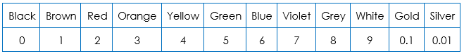
In the kit, a Resistor Color Code Calculator card is provided as shown below:
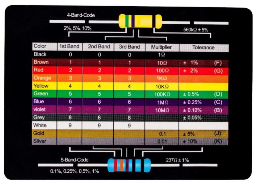
As shown in the card, each color stands for a number.
The 4- and 5-band resistors are frequently used, on which there are 4 and 5 chromatic bands. Let’s see how to read the resistance value of a 5-band resistor as shown below. Normally, when you get a resistor, you may find it hard to decide which end to start for reading the color. The tip is that the gap between the 4th and 5th band will be comparatively larger. Therefore, you can observe the gap between the two chromatic bands at one end of the resistor; if it’s larger than any other band gaps, then you can read from the opposite side.
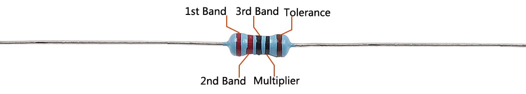
So for this resistor, the resistance should be read from left to right. The value should be in this format: 1st Band 2nd Band 3rd Band x 10^Multiplier (Ω) and the permissible error is ±Tolerance%. So the resistance value of this resistor is 2(red) 2(red) 0(black) x 10^0(black) Ω = 220 Ω, and the permissible error is ± 1% (brown).
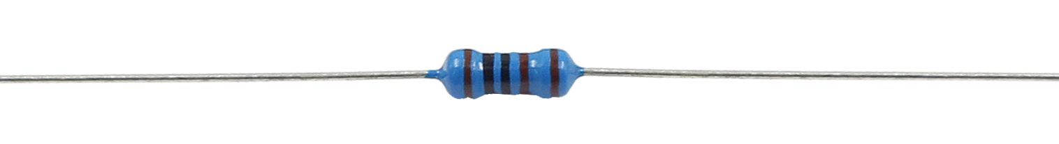
One more example. The resistance of the resistor below should be 1(brown) 0(black) 0(black) x 10^1(brown) Ω =100×10 Ω = 1000 Ω = 1KΩ, and the permissible error is ± 1%(brown). Now try it by yourself!
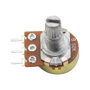
2.1.8 Potentiometer
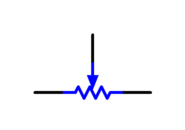
Potentiometer is also a resistance component with 3 terminals and its resistance value can be adjusted according to some regular variation. Potentiometer usually consists of resistor and movable brush. When the brush is moving along the resistor, there is a certain resistance or voltage output depending on the displacement. Figure (y) is the potentiometer and figure (j) is the corresponding circuit symbol. The middle pin in figure (z), represented by the arrow in Fig. (y) is the movable brush.
The functions of the potentiometer in the circuit are as follows:
1. Serving as a voltage divider
Potentiometer is a continuously adjustable resistor. When you adjust the shaft or sliding handle of the potentiometer, the movable contact will slide on the resistor. At this point, a voltage can be output depending on the voltage applied onto the potentiometer and the angle the movable arm has rotated to or the travel it has made.
2. Serving as a rheostat
When the potentiometer is used as a rheostat, connect the middle pin and one of the other 2 pins in the circuit. Thus you can get a smoothly and continuously changed resistance value within the travel of the moving contact.
3. Serving as a current controller
When the potentiometer acts as a current controller, the sliding contact terminal must be connected as one of the output terminals.
2.1.9 LED
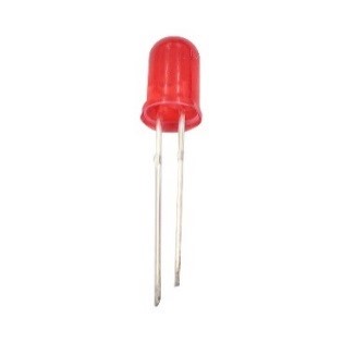
Semiconductor light-emitting diode is a type of component which can turn electric energy into light energy via PN junctions. By wavelength, it can be categorized into laser diode, infrared light-emitting diode and visible light-emitting diode which is usually known as light-emitting diode (LED).
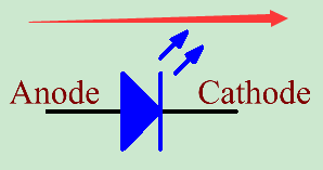
Diode has unidirectional conductivity, so the current flow will be as the arrow indicates in figure (l). You can only provide the anode with a positive power and the cathode with a negative. Thus the LED will light up.
In this kit, LEDs of red, green, yellow. An LED has two pins. The longer one is the anode, and shorter one, the cathode. Pay attention not to connect them inversely. There is fixed forward voltage drop in the LED, so it cannot be connected with the circuit directly because the supply voltage can outweigh this drop and cause the LED to be burnt. The forward voltage of the red, yellow, and green LED is 1.8 V. Most LEDs can withstand a maximum current of 20 mA, so we need to connect a current limiting resistor in series.
The formula of the resistance value is as follows:
R = (Vsupply – VD)/I
R stands for the resistance value of the current limiting resistor, Vsupply for voltage supply, VD for voltage drop and I for the working current of the LED.
If we provide 5V for the red LED, the minimum resistance of the current limiting resistor should be: (5V-1.8v)/20mA = 160Ω. Therefore, you need a 160Ω or larger resistor to protect the LED. You are recommended to use the 220Ω resistor offered in the kit.