Overview
In this lesson, you will learn about touch switch module. It can replace the traditional kinds of switch with these advantages: convenient operation, fine touch sense, precise control and least mechanical wear.
Components Required
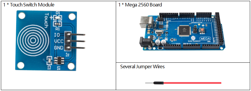
Component Introduction
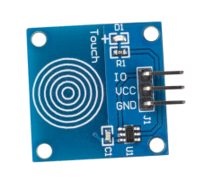
Touch switch module works by detecting a change in capacitance due to influence of an external object. The touch plate is covered with insulating material, and the user does not come in contact with the electrical circuit.
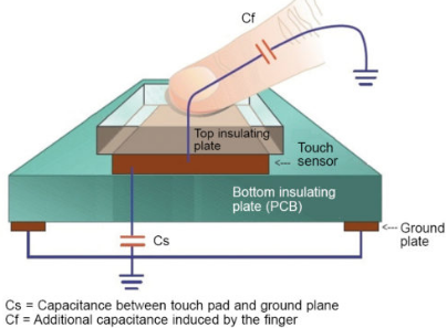
A capacitive touch switch has different layers—top insulating face plate followed by touch plate, another insulating layer and then ground plate.
In practice, a capacitive sensor can be made on a double-sided PCB by regarding one side as the touch sensor and the opposite side as ground plate of the capacitor. When power is applied across these plates, the two plates get charged. In equilibrium state, the plates have the same voltage as the power source.
The touch detector circuit has an oscillator whose frequency is dependent on capacitance of the touchpad. When a finger is moved close to the touchpad, additional capacitance causes frequency of this internal oscillator to change. The detector circuit tracks oscillator frequency at timed intervals, and when the shift crosses the threshold change, the circuit triggers a key-press event.
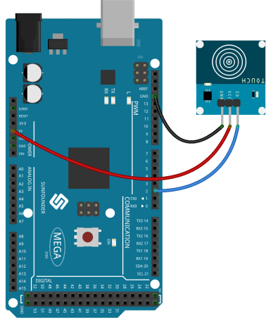
Fritzing Circuit
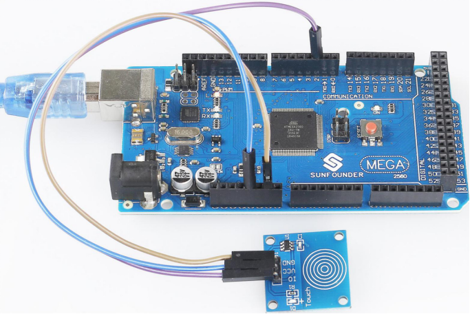
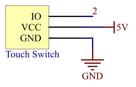
In this example, pin 2 is used to read the signal of Touch Switch Module.
Schematic Diagram
Code
void setup() {
  Serial.begin(9600);
  pinMode(2, INPUT);
}

void loop() {
  int touchState = digitalRead(2);
  Serial.println(touchState);
  delay(1);
}
Uploaded the codes to the Mega2560 board, you can see the readings of pins displaying on the serial monitor.
When your finger tip touches the Touch switch module, 「1」will be displayed on the serial monitor; and when you remove your finger, 「0」 will be be displayed. As for the detailed code explanation, you need to turn to Part 1-1.4 Digital Read.
Phenomenon Picture