Overview
In this lesson, you will learn how to use LED. LED is a kind of common light-emitting device that works according to the principle that the recombination of electron and hole releases energy to give out light. This component is used widely in the current society, such as illumination, panel display, medical device and so on.
Components Required
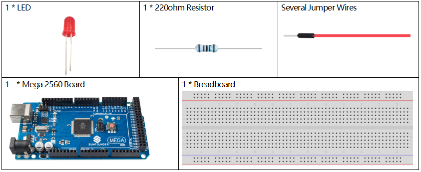
Component Introduction
Semiconductor light-emitting diode is a type of component which can turn electric energy into light energy via PN junctions. By wavelength, it can be categorized into laser diode, infrared light-emitting diode and visible light-emitting diode which is usually known as light-emitting diode (LED).
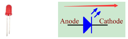
Diode has unidirectional conductivity, so the current flow will be as the arrow indicates in figure circuit symbol. You can only provide the anode with a positive power and the cathode with a negative. Thus the LED will light up.
An LED has two pins. The longer one is the anode, and shorter one, the cathode. Pay attention not to connect them inversely. There is fixed forward voltage drop in the LED, so it cannot be connected with the circuit directly because the supply voltage can outweigh this drop and cause the LED to be burnt. The forward voltage of the red, yellow, and green LED is 1.8 V and that of the white one is 2.6 V. Most LEDs can withstand a maximum current of 20 mA, so we need to connect a current limiting resistor in series.
The formula of the resistance value is as follows:
R = (Vsupply – VD)/I
R stands for the resistance value of the current limiting resistor, Vsupply for voltage supply, VD for voltage drop and I for the working current of the LED.
If we provide 5 voltage for the red LED, the minimum resistance of the current limiting resistor should be: (5V-1.8v)/20mA = 160Ω. Therefore, you need a 160Ω or larger resistor to protect the LED. You are recommended to use the 220Ω resistor offered in the kit.
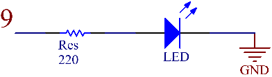
Schematic Diagram
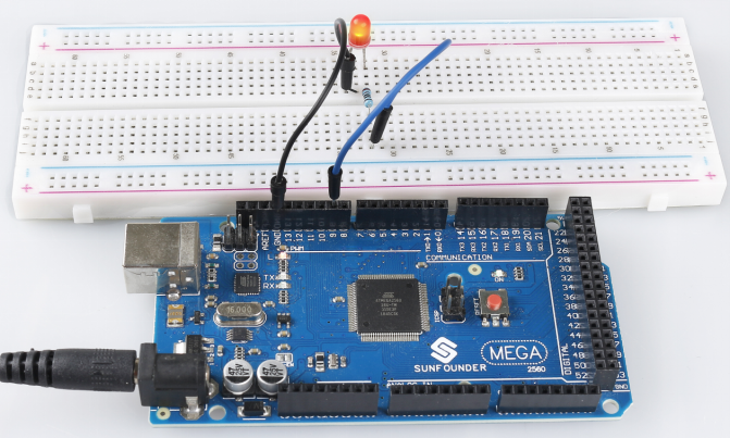
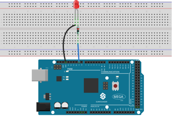
Fritzing Circuit
In this example, we use pin 9 to drive LED. Insert one side of the resistor in the digital pin 9 and connect the longer pin (a positive electrode, referred to as anode) of the LED with the other side of the resistor. Extend the shorter pin (a negative electrode, referred to as cathode) of the LED to GND.
Code
Example 1:
const int ledPin = 9;

void setup()
{
  pinMode(ledPin, OUTPUT);
}

void loop()
{
  digitalWrite(ledPin, HIGH);
  delay(1000);
  digitalWrite(ledPin,LOW);
  delay(1000);
}
Finished uploading the codes to the Mega2560 board, you can see the LED flashing. Refer to Part 1-1.2 Digital Write to check the detail code explanation.
Example 2:
int ledPin = 9;
void setup()
{
}
void loop()
{
  for (int value = 0 ; value <= 255; value += 5)
  {
    analogWrite(ledPin, value);
    delay(30);
  }
}
After uploading the codes to the Mega2560 board, you can see the LED getting brighter, then turning off, getting brighter, then turning off again…this loop will continue in this way. About the detail code explanation, please refer to Part 1-1.3 Analog Write.
Phenomenon Picture