Overview
In this lesson, you will learn something about Joystick. The basic idea of a joystick is to translate the movement of a stick into electronic information that a computer can process. It can be applied to work as the controller of devices, such as robot.
Components Required
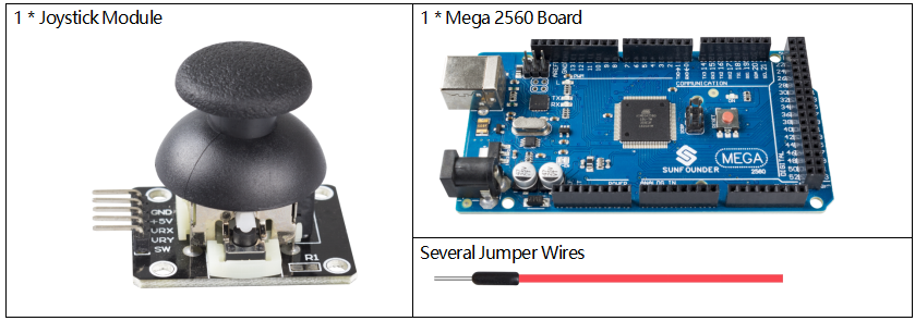
Component Introduction
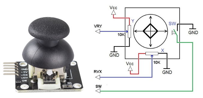
In order to communicate a full range of motion to the computer, a joystick needs to measure the stick’s position on two axes — the X-axis (left to right) and the Y-axis (up and down). Just as in basic geometry, the X-Y coordinates pinpoint the stick’s position exactly.
To determine the location of the stick, the joystick control system simply monitors the position of each shaft. The conventional analog joystick design does this with two potentiometers, or variable resistors.
The joystick also has a digital input that is actuated when the joystick is pressed down.
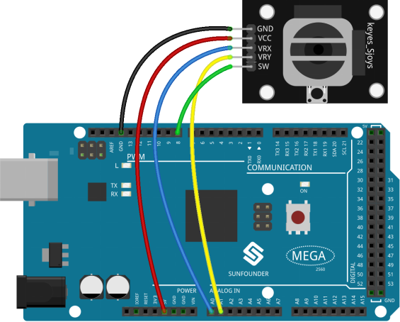
Fritzing Circuit
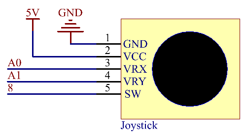
In this example, we get the GND of the Joystick extended to connect with GND, VCC with 5V, VRX with pin A0. After that, we make VRY connect with pin A1, SW connect with pin 8.
Schematic Diagram
Code
const int xPin = A0;  //the VRX attach to
const int yPin = A1;  //the VRY attach to
const int swPin = 8;  //the SW attach to

void setup()
{
  pinMode(swPin, INPUT);  //set the SW pin to INPUT
  digitalWrite(swPin, HIGH);   //And initial value is HIGH
  Serial.begin(9600);
}

void loop()
{
  Serial.print("X: ");
  Serial.print(analogRead(xPin), DEC);  // print the value of VRX in DEC
  Serial.print("|Y: ");
  Serial.print(analogRead(yPin), DEC);  // print the value of VRX in DEC
  Serial.print("|Z: ");
  Serial.println(digitalRead(swPin));   // print the value of SW
  delay(500);
}
Uploaded the codes to the Mega2560 board, you can open the serial monitor to see readings on the X-axis and Y-axis of Joystick, as well as the button status of Z-axis. The values of the X-axis and Y-axis are the analog values, which vary within the range「0」~「1023」. The Z-axis shows numerical value and the state is either 「1」 or 「0」. Refer to Part 1-1.5 Analog Read and 1.4 Digital Read to check the code explanation.
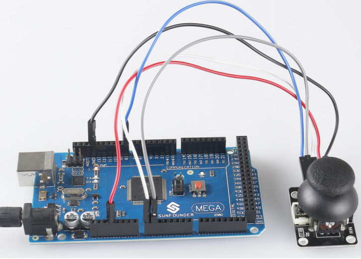
Phenomenon Picture