Overview
In this lesson, you will learn about Rotary Encoder. A rotary encoder is an electronic switch with a set of regular pulses in strictly timing sequence. When used with IC, it can achieve increment, decrement, page turning and other operations such as mouse scrolling, menu selection, and so on.
Components Required
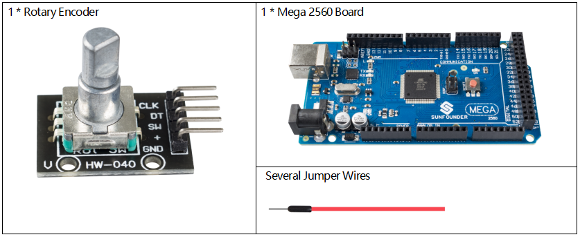
Component Introduction
There are mainly two types of rotary encoders: absolute and incremental (relative) encoders. An incremental one is used in this experiment.
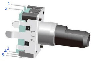
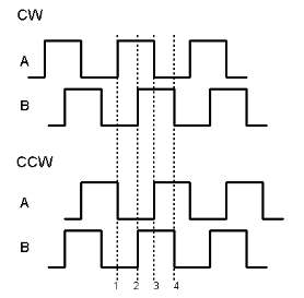
Most rotary encoders have 5 pins with three functions of turning left & right and pressing down. Pin 1 and pin 2 are switch wiring terminals used to press. Pin 4 is generally connected to ground. Pin 3 and pin 5 are first connected to a pull-up resistor and then to VCC and they can generate two-phase square waves whose phase difference is 90°. Usually these waves are called channel A and channel B as shown below:
As shown on the right, when channel A changes from high level to low level, if channel B is high level, it indicates the rotary encoder spins clockwise (CW); if at that moment channel B is low level, it means spins counterclockwise (CCW). So if we read the value of channel B when channel A is low level, we can know in which direction the rotary encoder rotates.
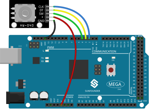
Fritzing Circuit
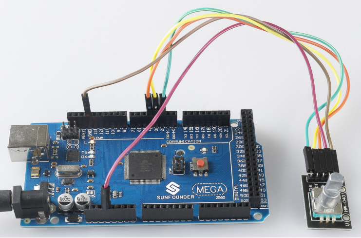
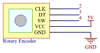
In this example, we can connect the Rotary Encoder pin directly to the Mega 2560 Board pin, connect the GND of the Rotary Encoder to GND, 「+」 to 5V, SW to digital pin 4, DT to digital pin 3, and CLK to digital pin 2.
Schematic Diagram
Code
const int clkPin= 2; //the clk attach to pin2
const int dtPin= 3; //the dt attach to pin3
const int swPin= 4 ;//the number of the button
int encoderVal = 0;
void setup()
{
  //set clkPin,dePin,swPin as INPUT
  pinMode(clkPin, INPUT);
  pinMode(dtPin, INPUT);
  pinMode(swPin, INPUT);
  digitalWrite(swPin, HIGH);
  Serial.begin(9600); // initialize serial communications at 9600 bps
}
void loop()
{
  int change = getEncoderTurn();
  encoderVal = encoderVal + change;
  if(digitalRead(swPin) == LOW)//if button pull down
  {
    encoderVal = 0;
  }
  Serial.println(encoderVal); //print the encoderVal on the serial monitor
}
int getEncoderTurn(void)
{
  static int oldA = HIGH; //set the oldA as HIGH
  static int oldB = HIGH; //set the oldB as HIGH
  int result = 0;
  int newA = digitalRead(dtPin);//read the value of clkPin to newA
  int newB = digitalRead(clkPin);//read the value of dtPin to newB
  if (newA != oldA || newB != oldB) //if the value of clkPin or the dtPin has changed
  {
    // something has changed
    if (oldA == HIGH && newA == LOW)
    {
      result = (oldB  * 2 - 1);
    }
  }
  oldA = newA;
  oldB = newB;
  return result;
}
You will see the angular displacement of the rotary encoder printed on Serial Monitor. When you turn the rotary encoder clockwise, the angular displacement is increased; when turn it counterclockwise, the displacement is decreased. If you press the switch on the rotary encoder, the readings will return to zero.
Code Analysis
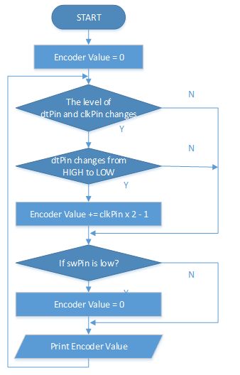
When Rotary Encoder is used, the following situations of pin level will occur.
① When rotating the shaft, dtPin will go from high level to low level.
② clkPin will remain high level when the shaft rotates clockwise, otherwise it goes low level.
③ When the shaft is pressed, swPin will have low level.
From this, the program flow is shown on the right.
For detailed analysis of potential state change judgment, please refer to Part 1-1.10 State Change Detection.
Phenomenon Picture