Overview
In this lesson, you will learn something about 7-Segment Display. 7-Segment Display has so many advantages that it is widely used in electrical equipments, especially in household appliances that display numerical information, such as display, air conditioner, water heater, refrigerator and so on. LEDs on the 7-Segment Display emit light by the input of different electrical signals to the different pins of it. The numerical information it can display includes time, date, temperature and so on.
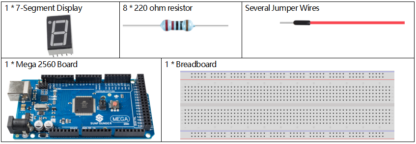
Components Required
Component Introduction
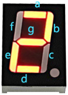
A 7-segment display is an 8-shaped component which packages 7 LEDs. Each LED is called a segment – when energized, one segment forms part of a numeral to be displayed.
There are two types of pin connection: Common Cathode (CC) and Common Anode (CA). As the name suggests, a CC display has all the cathodes of the 7 LEDs connected when a CA display has all the anodes of the 7 segments connected. In this kit, we use the former.
Each of the LEDs in the display is given a positional segment with one of its connection pins led out from the rectangular plastic package. These LED pins are labeled from “a” through to “g” representing each individual LED. The other LED pins are connected together forming a common pin. So by forward biasing the appropriate pins of the LED segments in a particular order, some segments will brighten and others stay dim, thus showing the corresponding character on the display.

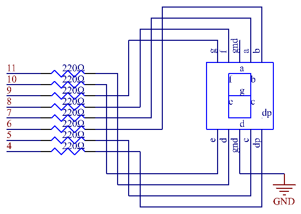
Fritzing Circuit
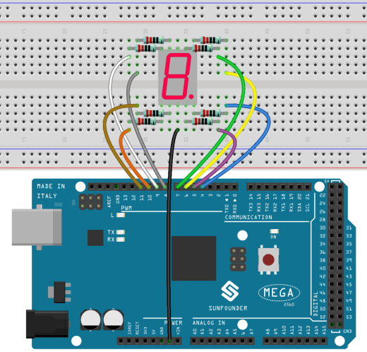
Connect each of pin a-g of the 7-Segment Display to one 220ohm current limiting resistor respectively and then to pin 4–11. GND connects to GND.
The wiring between the 7-segment display and the Mega2560 board as shown below :
Schematic Diagram
Code
const int a=7; //a of 7-segment attach to digital pin 7
const int b=6; //b of 7-segment attach to digital pin 6
const int c=5; //c of 7-segment attach to digital pin 5
const int d=11;//d of 7-segment attach to digital pin 11
const int e=10;//e of 7-segment attach to digital pin 10
const int f=8; //f of 7-segment attach to digital pin 8
const int g=9; //g of 7-segment attach to digital pin 9
const int dp=4;//dp of 7-segment attach to digital pin 4

void setup()
{
  //loop over thisPin from 4 to 11 and set them all to output
  for(int thisPin = 4;thisPin <= 11;thisPin++)
  {
    pinMode(thisPin,OUTPUT);
  }
  digitalWrite(dp,LOW);//turn the dp of the 7-segment off
}

void loop()
{
  digital_1();//diaplay 1 to the 7-segment
  delay(1000);//wait for a second
  digital_2();//diaplay 2 to the 7-segment
  delay(1000);//wait for a second
  digital_3();//diaplay 3 to the 7-segment
  delay(1000);//wait for a second
  //...
}

void digital_1(void) //diaplay 1 to the 7-segment
{
  digitalWrite(c,HIGH);//turn the c of the 7-segment on
  digitalWrite(b,HIGH);//turn the b of the 7-segment on
  for(int j = 7;j <= 11;j++)//turn off the others
  digitalWrite(j,LOW);
}

void digital_2(void) //diaplay 2 to the 7-segment
{
  //...
}

void digital_3(void) //diaplay 3 to the 7-segment
{
  //...
}
//...
NOTE: A small portion of the codes are omitted. Please check the complete codes by opening 2.5_7segment.ino in path of sunfounder_vincent_kit_for_arduino\code\2.5_7segment in Arduino IDE.
Once upload the codes, you can see the 7-segment display displaying 1, 2, 3, 4, 5, 6, 7, 8, 9, A, b, C, d, E, F in sequence.
Code Analysis
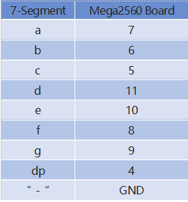
Take the pin numbers on 7-segment as names, and declare the pins on the Mega2560 board.
const int a=7; //a of 7-segment attach to digital pin 7
const int b=6; //b of 7-segment attach to digital pin 6
const int c=5; //c of 7-segment attach to digital pin 5
const int d=11;//d of 7-segment attach to digital pin 11
const int e=10;//e of 7-segment attach to digital pin 10
const int f=8; //f of 7-segment attach to digital pin 8
const int g=9; //g of 7-segment attach to digital pin 9
const int dp=4;//dp of 7-segment attach to digital pin 4
Install a series of subfunctions to package the level state at each block during the number display of the 7-segment. For example, when the character 「2」 is displayed, the block F and the block c are turn off; the other blocks are lit up.
First we need to know how it looks like when display the numeral 2 on the 7-Segment display. It’s actually the segments a, b, d, e and g are power on, which generates the display of 2. In programming, pins connected to these segments are set High level when c and f are Low level. Here we use a for() statement to set these pins as High level respectively (the braces after for() are deleted as there is only one line). Connect pin dp to pin 4; it’s already defined as LOW in setup().
After running this part, the 7-segment will display 2. Similarly, the display of other characters are the same. Since the letters b and d in upper case, namely B and D, would look the same with 8 and 0 on the display, they are displayed in lower case instead.
...
void digital_2(void) //diaplay 2 to the 7-segment
{
  digitalWrite(b,HIGH);
  digitalWrite(a,HIGH);
  for(int j = 9;j <= 11;j++)
  digitalWrite(j,LOW);
  digitalWrite(c,LOW);
  digitalWrite(f,LOW);
}
...
In loop(), call the function that displays the number.
...
void digital_2(void) //diaplay 2 to the 7-segment
{
digitalWrite(b,HIGH);
digitalWrite(a,HIGH);
for(int j = 9;j <= 11;j++)
digitalWrite(j,LOW);
digitalWrite(c,LOW);
digitalWrite(f,LOW);
}
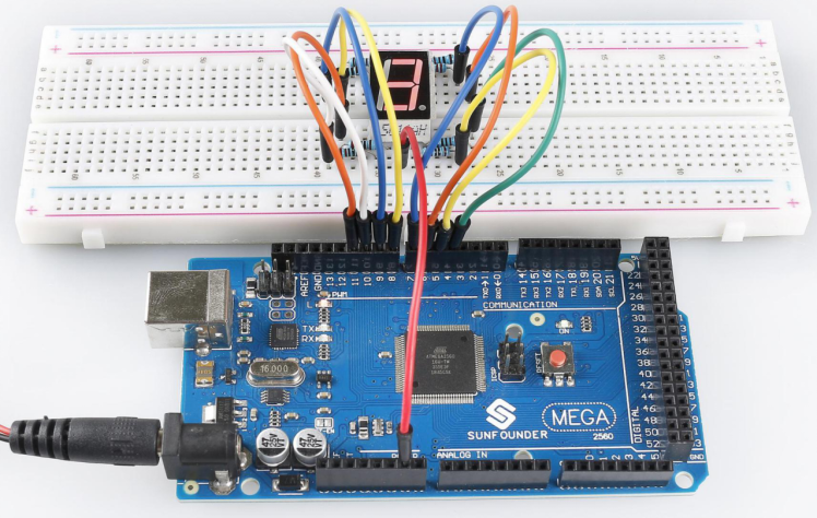
... Phenomenon Picture