Overview
In this lesson, you will learn about LED Matrix Module. LED Matrix Module uses the MAX7219 driver to drive the 8 x 8 LED Matrix.
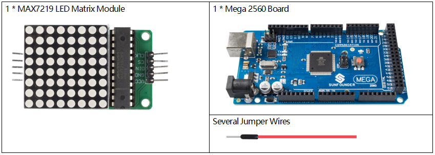
Components Required
Component Introduction
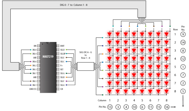
The 64 LEDs are driven by 16 output pins of the IC. The maximum number of LEDs light up at the same time is actually eight. The LEDs are arranged as 8×8 set of rows and columns. So the MAX7219 activates each column for a very short period of time and at the same time it also drives each row. So by rapidly switching through the columns and rows the human eye will only notice a continuous light.
MAX7219
These integrated circuits from Maxim are for driving either 64 individual LED’s, or up to 8 digits of 7-segment displays. The drivers implement a SPI compatible slave interface that can be controlled from the Arduino using only 3 of the digital output pins.
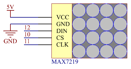
Fritzing Circuit
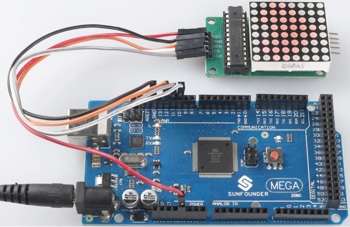
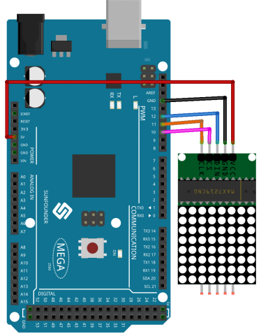
In this example, we get the VCC pin of MAX7219 connected to 5V, GND to ground, DIN to digital pin 12, CS to digital pin 10, CLK to digital pin 11.
Schematic Diagram
Code
The codes use the library LedControl.h, and please refer to Part 4 – 4.1 Add Libraries to add in the library to Arduino IDE.
#include "LedControl.h"
LedControl lc = LedControl(12, 11, 10, 1);

void setup()
{
  lc.shutdown(0, false);
  lc.setIntensity(0, 5);
  lc.clearDisplay(0);
}

void loop()
{
  displayDot();  displayCol();
  displayRow();  displayPic();
}

void displayDot()
{
  lc.clearDisplay(0);
  delay(100);
  for (int row = 0; row < 8; row++)
  {
    for (int col = 0; col < 8; col++)
    {
      lc.setLed(0, row, col, true);
      delay(50);
    }
  }
}

void displayCol()
{
  lc.clearDisplay(0);
  delay(100);
  byte data = B01100110;
  for (int col = 0; col < 8; col++)
  {
    lc.setColumn(0, col, data);
    delay(100);
  }
}

void displayRow()
{
  lc.clearDisplay(0);
  delay(100);
  byte data = B10011001;
  for (int row = 0; row < 8; row++)
  {
    lc.setRow(0, row, data);
    delay(100);
  }
}

void displayPic()
{
  lc.clearDisplay(0);
  delay(100);
  byte pic[8] =
  {
    B00000000,
    B01100110,
    B11111111,
    B11111111,
    B01111110,
    B00111100,
    B00011000,
    B00000000};
  for (int col = 0; col < 8; col++)
  {lc.setColumn(0, col, pic[col]);}
  delay(2000);
}
After the codes are uploaded, you can see that the LEDs turn on in the sequence of a column, a row or a dot or there is a picture appearing on the LED matrix.
Code Analysis
By calling the library LedControl.h, you can easily use the LED matrix.
#include "LedControl.h"Library Functions:
LedControl(int dataPin,int clockPin,int csPin,int numDevices)Create an instance of type LedControl through which we talk to the MAX7219 devices. The initialization of an LedControl takes 4 arguments.
dataPin,clockPin,csPin: The first 3 arguments are the pin-numbers on the Arduino that are connected to the MAX7219. You are free to choose any of the digital IO-pins on the arduino, but since some of the pins are also used for serial communication or have a led attached to them its best to avoid pin 0,1 and 13.
numDevices: The fourth argument is the number of cascaded MAX7219 devices you’re using with this LedControl. The library can address up to 8 devices from a single LedControl-variable.
void shutdown(int addr, bool b)addr: The address of the display to control.
b: If true the device goes into power-down mode. If false device goes into normal operation.
void setIntensity(int addr, int intensity)Themethod lets you control brightness in 16 discrete steps. Larger values make the display brighter up to the maximum of 15.
addr: The address of the display to control.
intensity: the brightness of the display. Only values between 0(darkest) and 15(brightest) are valid.
void clearDisplay(int addr)All LEDs off after this one.
addr: The address of the display to control.
void setLed(int addr, int row, int col, boolean state)Set the status of a single Led.
addr: The address of the display to control.
row: The row of the Led (0..7).
col: The column of the Led (0..7).
state: If true the led is switched on, if false it is switched off.
void setRow(int addr, int row, byte value)Set all 8 LEDs in a row to a new state.
addr: The address of the display to control.
row: Row which is to be set (0..7).
value: Each bit set to 1 will light up the corresponding Led.(e.g. B01000000 will light up the 2nd).
void setColumn(int addr, int col, byte value)Set all 8 LEDs in a row to a new state.
addr: The address of the display to control.
col: Column which is to be set (0..7).
value: Each bit set to 1 will light up the corresponding Led.(e.g. B01000000 will light up the 2nd).
Phenomenon Picture