Introduction
Welcome to the first, the most basic, and the zero level experiment – blinking LED! As your first step into the fascinating Arduino/programming/physical world, here it would be simple at each step: simple principle, simple wiring, and simple code. So get bold and let’s begin!
Components
– 1 * SunFounder Mars/Mercury Board (Mars board as an example)
– 1 * Breadboard
– 1 * USB cable
Principle
There is a built-in LED(L) connected to pin13 of both the Mars and Mercury board. The circuit diagram:
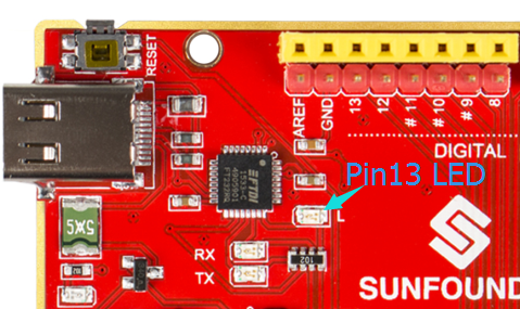

In this experiment, connect pin13 to a 1K current-limiting resistor (to protect the LED from burning) and then to the anode of an LED, and connect the cathode of the LED to GND. Pin13 is a digital port with only two statuses: 0 or LOW (0V), and 1 or HIGH (5V). The LED will light up when pin13 is HIGH (5V) level and go out when it’s LOW (0V). We can control pin13 to output HIGH and LOW alternately by programming, so the LED flickers.
Experimental Procedures
Step 1: Connect the board and the computer with a USB cable
Step 2: Write the code
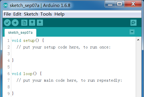
A typical Arduino program consists of two subprograms: setup() for initialization and loop() which contains the main body of the program. You can see it when you open an empty program.
Setup()
This subprogram is used for preparations such as to define the input and output of the pins, set the baud rate of the serial communication, etc.
Go to set the input and output status of pin13. Since it is a digital pin, we need to define whether it’s an input or output before writing a value to it, so as to ensure the stability of the pin.
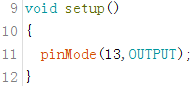
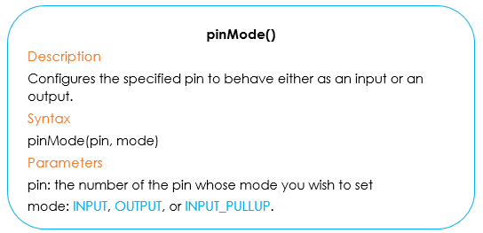
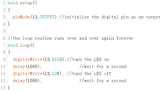
Here we use the pinMode() function to set the input and output status of the pin. PinMode(13, OUTPUT) means setting pin13 as output, indicating you can write a value to it. Note that the code is case sensitive and the line ends with a semicolon “;”. The void before the setup() indicates that this function will not return a value. Please note that setup() begins with a curly brace “{” and ends with another “}”; this pair is indispensable.
Loop()
Since loop () contains the main body of the program, from it you can tell what the code is all about. It’s a recurring process and won’t stop unless some conditions are met or the Arduino board has been cut off power and stopped forcibly. So if you want to make the LED at pin13 keep blinking, you can just change the High and Low level in turn at pin 13 in loop().
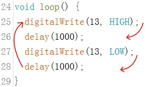
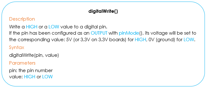
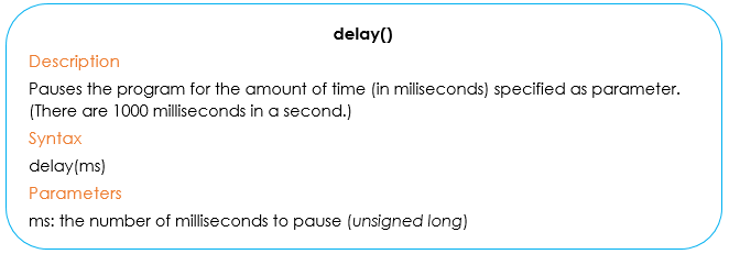
Here we use the digitalWrite() function to write a value to pin13. digitalWrite(13,HIGH) is to set the digital pin13 as High level, thus the LED lights up; delay(1000) is to delay the program for 1000ms(1s) before the following code, meaning the LED will light for 1s. Similarly, digitalWrite(13, LOW) is to set pin13 as Low level, thus to dim the LED.
Also delay(1000) is to make LED keep dim for 1s. A cycle has been completed then, and back to digitalWrite(13, HIGH). So in the whole course, you will see the pin13 LED keep blinking.
The code for blinking an LED is done now. You can change the frequency of blinking by modifying the parameter in delay(). In the code below, the words in grey after the double slashes “//” are the COMMENTS of the code before. It’s a good habit to comment your code for sharing and your own convenience in case of self-checking.
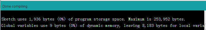
Step 3: After the code is finished, remember to save. Click  to compile the code. Check whether there’s any error. It indicates no error if you see the messages at the bottom as below.
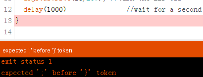
1) But if messages in orange appear, it indicates there’re some problems with your code and you need to modify according to the prompts. As the error ‘;’ before ‘}’ token shown below, we will know there lacks of a semicolon after the delay (1000) before the line highlighted.
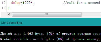
Add a semicolon and it can then be compiled successfully.
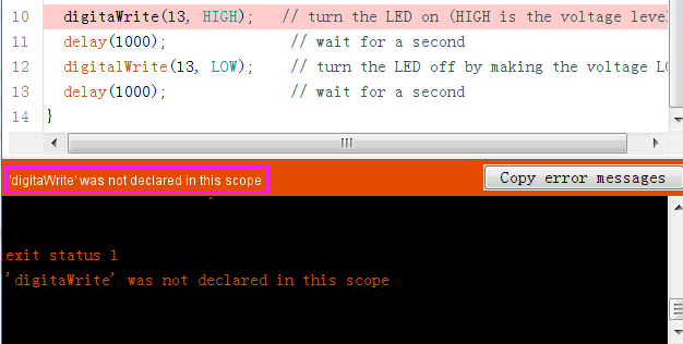
1) When the color of the code changes into black and a prompt ‘xx’ was not declared in this scope appears, it means xx is spelt wrong. Please check carefully (it should be “digitalWrite” here). After all is corrected, click Compile and it’ll be done in a while.
When writing the code, mistakes are inevitable. Embrace them and find the solution and learn the lesson from the mistakes. That’s the quickest path to master programming.
Step 4: Select the correct Board and Port, upload the sketch to the board.
You should now see the LED blinking.