Introduction
After the beginning ultra-simple experiment of blinking an LED, let’s try something interesting – gradually changing the luminance of an LED through programming. Since the pulsing light looks like breathing, we give it a magical name – breathing LED. We’ll accomplish this effect with pulse width modulation (PWM).
Components
– 1 * SunFounder Mars/Mercury Board (Mars board as an example)
– 1 * Breadboard
– 1 * LED
– 1 * Resistor (220Ω)
– 1 * USB cable
– Jumper wires
PWM
Pulse width modulation, or PWM, is a technique for getting analog results with digital means. Digital control is used to create a square wave, a signal switched between on and off. This on-off pattern can simulate voltages in between full on (5 Volts) and off (0 Volts) by changing the portion of the time the signal spends on versus the time that the signal spends off. The duration of “on time” is called pulse width. To get varying analog values, you change, or modulate, that width. If you repeat this on-off pattern fast enough with some device, an LED for example, it would be like this: the signal is a steady voltage between 0 and 5V controlling the brightness of the LED. (See the PWM description on the official website of Arduino).
In the graphic below, the green lines represent a regular time period. This duration or period is the inverse of the PWM frequency. In other words, with Arduino’s PWM frequency at about 500Hz, the green lines would measure 2 milliseconds each.
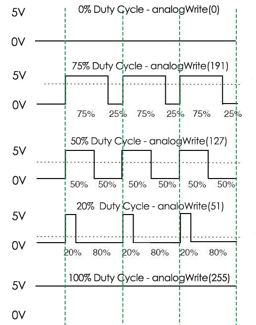
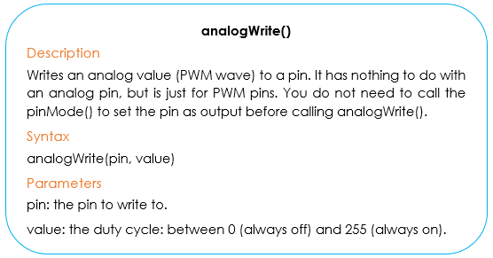
A call to analogWrite() is on a scale of 0 – 255 – analogWrite(255) requests a 100% duty cycle (always on), and analogWrite(127) is a 50% duty cycle (on half the time) for example. You will find that the smaller the PWM value is, the smaller the value will be after being converted into voltage. Then the LED becomes dimmer accordingly. Therefore, we can control the brightness of the LED by controlling the PWM value.
Principle
The built-in LED on the board is used in the last experiment, which is quite convenient. In this experiment, let’s try an external one which is more obvious to show the luminance change.
The schematic diagram:
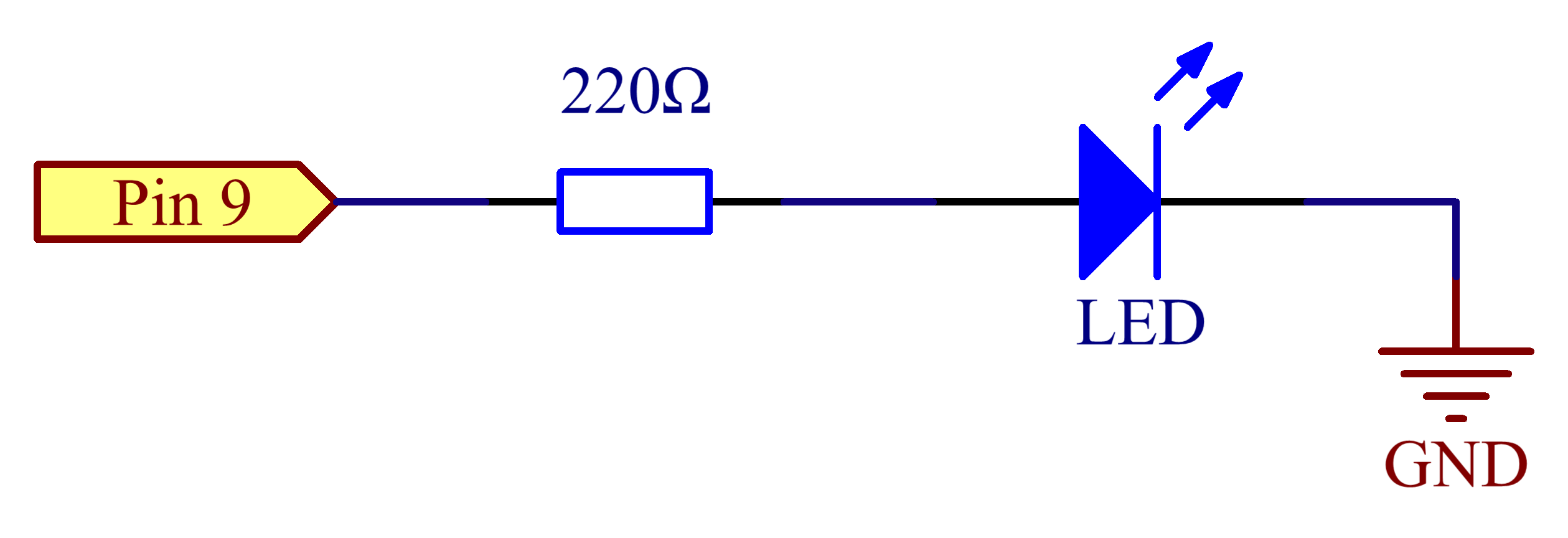
By programming, we can use the analogWrite() function to write different values to pin 9. The luminance of the LED will change accordiingly. On the SunFounder Mars/Mercury Board (Mars for example), pin 3, 5, 6, 9, 10, and 11 are the PWM pins (marked with “#” in the label). You can connect any of these pins for PWM signals.
Experimental Procedures
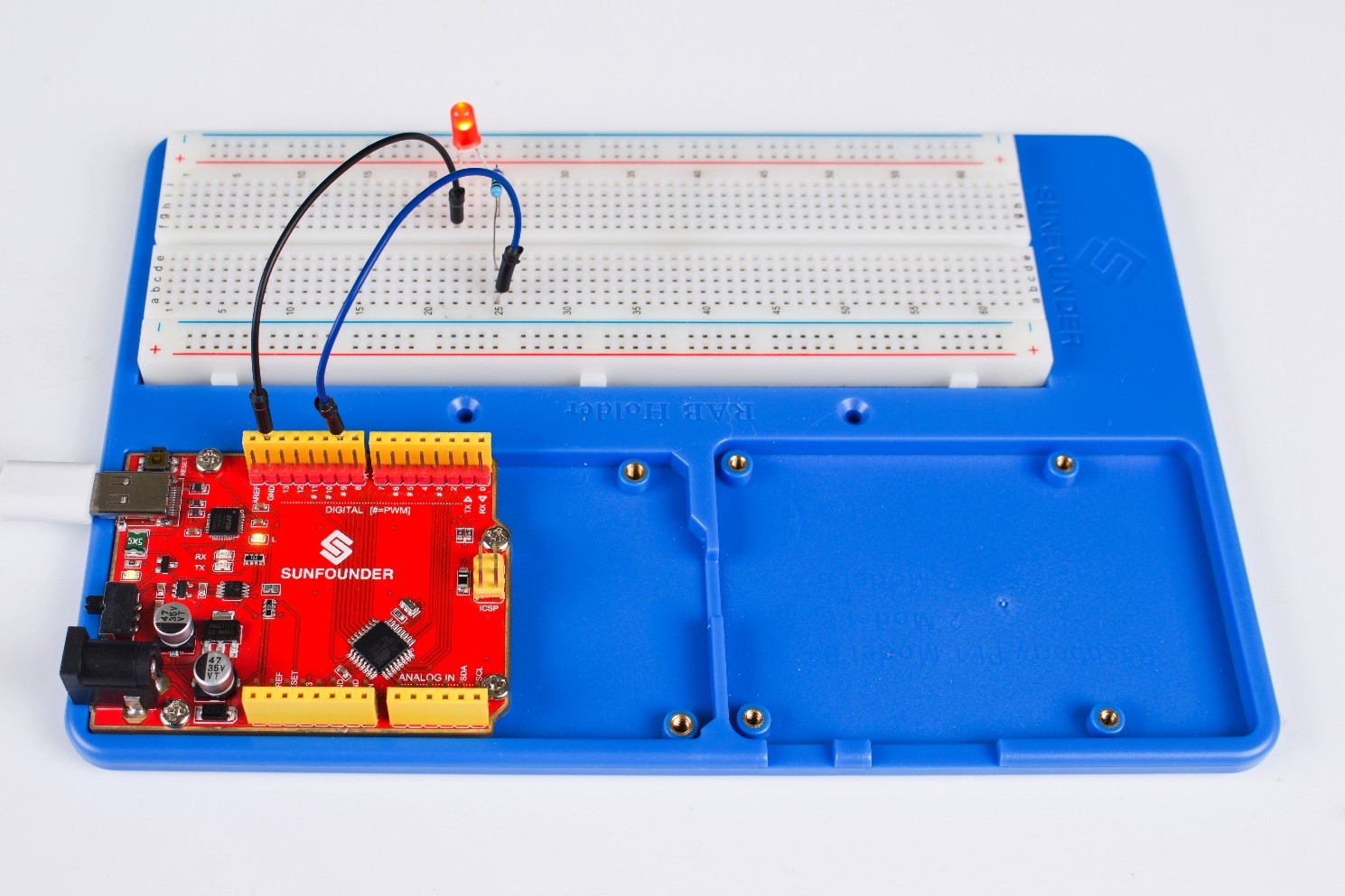
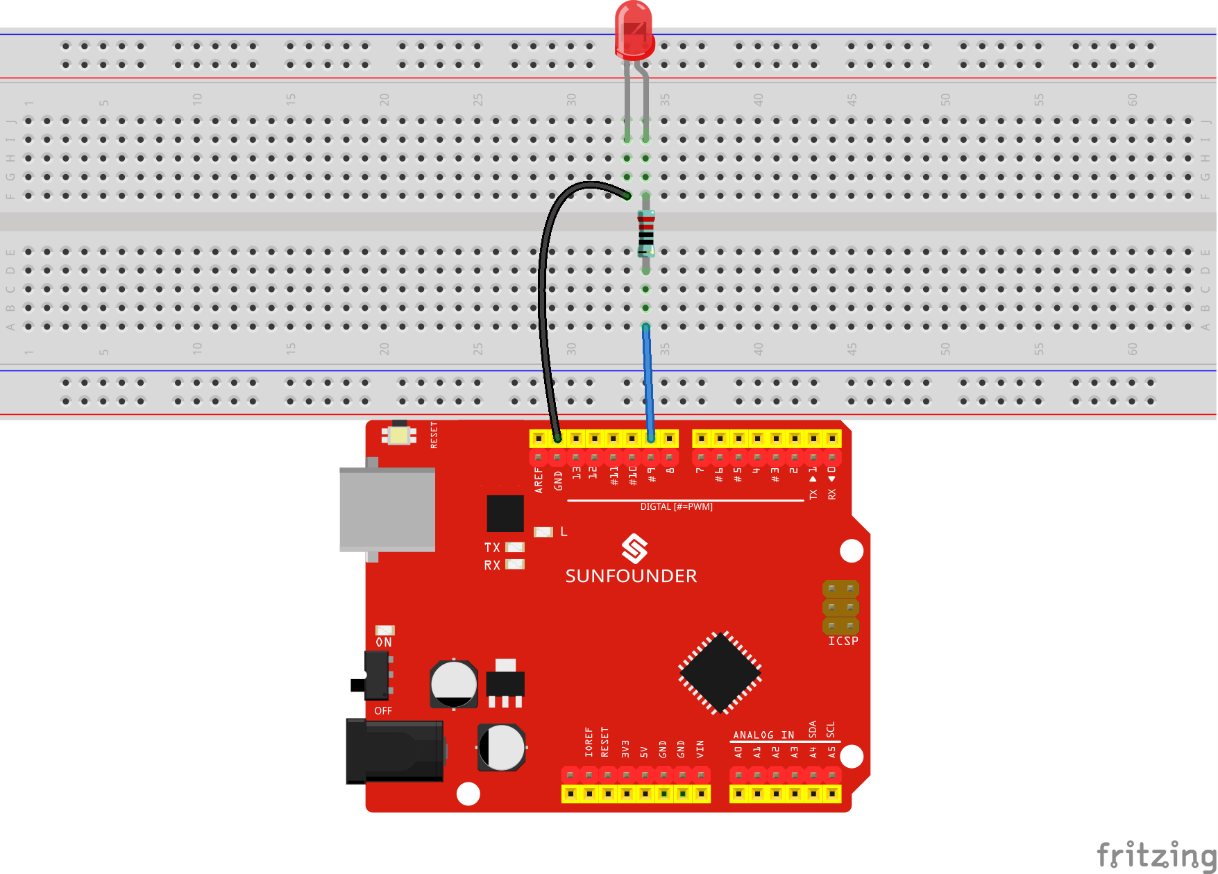
Step 1: Build the circuit
Step 2: Write the code
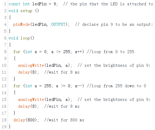
1) Define the variables first, it’s an effective way when you want to change the pin: you only need to replace 9 with another pin number, needless of changing the value one by one.

In this experiment, the LED has been connected to a current-limiting resistor and then pin9. So we define a const int, or constant integer, ledPin to store the value of pin9. ledPin stands for pin9 in the subsequent part.
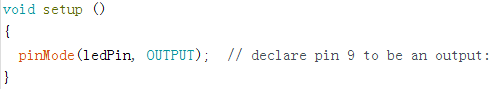
2) Set the pin 9 as output in setup(). Note that you need to set the input or output status of the digital pins before writing a value to them.
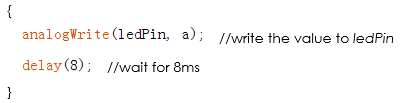
3) Set the workflow of the LED in loop().
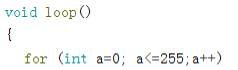
//When a=0, which accords with the condition a<=255, a++ equals to 1 (here in a = a + 1, the two “a”s are not the same, but anow = abefore + 1). Run the code in the curly braces: write a=0 into ledpin, wait for 8ms and exit the loop in the curly braces. Repeat the for() statement until a>255, then exit this loop.
The for() statement is used to repeat a block of statements enclosed in curly braces. Note: There is no semicolon behind the for() statement.Here the statement is to accumulate the value within 0-255 and writing it to ledPin one by one. The LED will become brighter as the value increases.
Go on to make the LED dimmer. Here we also use the for() statement.
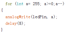
In the last case, we increased the value of ledPin from 0 to 255 gradually to make the LED grow brighter, so now decrease it from 255 to 0. The LED will slowly dim as the value descends.
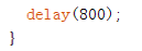
To make the phenomenon more obvious, use delay(800) to delay the last status (ledPin=0).
The complete code is as follows.
Step 3: After compiling the code successfully, select the correct Board and Port. Upload the sketch to the board.
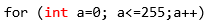
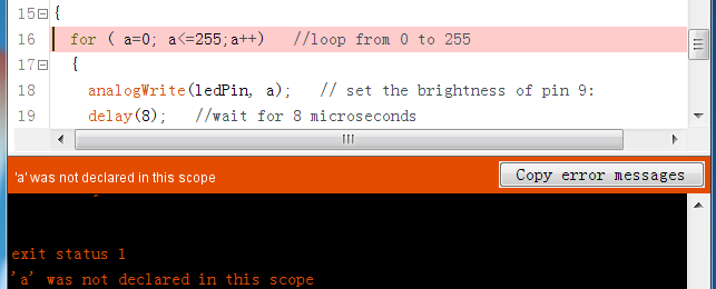
Note: Every new value should be defined before being applied. Otherwise, the error “’xx’ was not declared in this scope” will appear. Here define a as an integer:
Here you should see the LED gets brighter and brighter, then slowly dimmer, and again brighter and dimmer repeatedly, just like the breathing.