Introductioon
We’ve known how to set the value of digital pins in the previous experiments. Let’s see the analog pins (pins begin with A on the board) in this lesson. Connect one potentiometer to the analog pin A0, and you can know the partial pressure of potentiometer by reading the value of A0.
Components
– 1 * SunFounder Mars/Mercury Board (Mars board as an example)
– 1 * Breadboard
– 1 * Potentiometer
– 1 * USB cable
– Jumper wires
Analog V.S. Digital
A linear potentiometer is an analog electronic component. So what’s the difference between an analog value and a digital one? Simply put, digital means on/off, high/low level with just two states, i.e. either 0 or 1. But the data state of analog signals is linear, for example, from 1 to 1000; the signal value changes continuously over time instead of indicating an exact number. Analog signals include those of light intensity, humidity, temperature, and so on.
Serial Monitor
We will use a new tool in this experiment –Serial Monitor.
Serial Monitor is used for communication between the Uno board and a computer or other devices. It is a built-in software in the Arduino environment and you can click the button on the upper right corner to open it. You can send and receive data via the serial port on the control board and control the board by input from the keyboard.

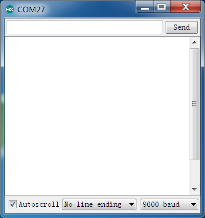
Here, the Serial Monitor serves as a transfer station for communication between your computer and the SunFounder Uno board. First, the computer transfers data to the Serial Monitor, and then the data is read by the Uno board. Finally, the Uno will perform related operations. Click the icon at the top right corner and a window will pop up as shown below:
Principle
The schematic diagram:
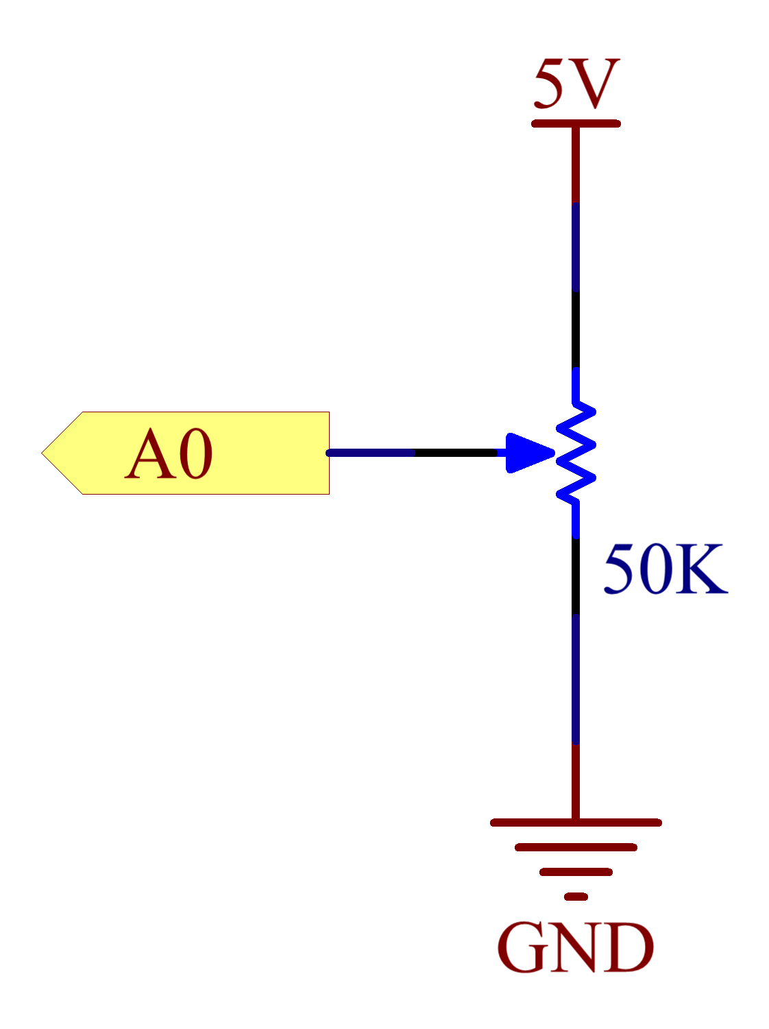
Here the potentiometer (pot) is used for dividing the voltage. Connect the middle pin of the pot to A0, the rest pins to 5V and GND respectively. Spin the knob of the potentiometer – turn it towards the pin connected to GND, and the voltage at pin A0 will reduce; the voltage value will be converted to a digital value via the AD converter on the board. Then you can see the data in Serial Monitor. When you spin the knob towards the pin connected to 5V, voltage increases, and the digital value in the window will increase.
Experimental Procedures
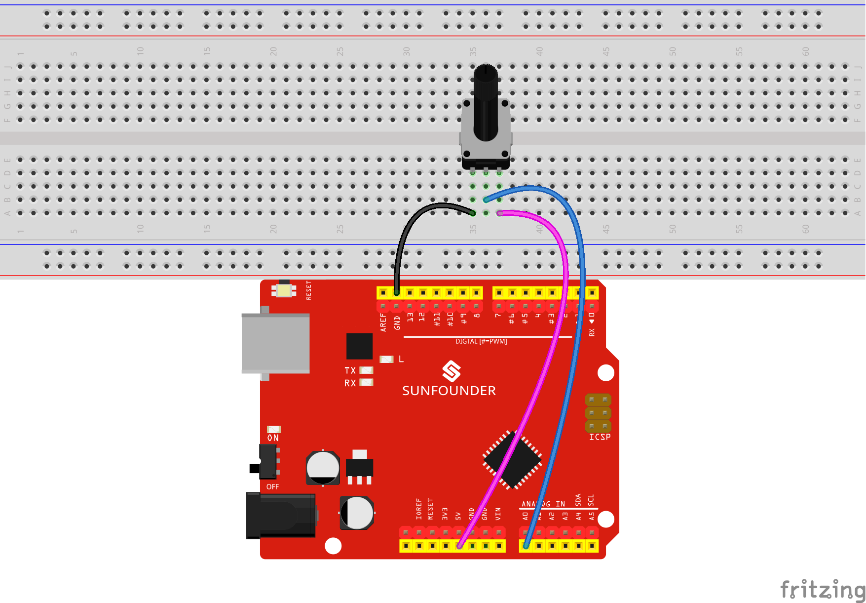
Step 1: Build the circuit
Step 2: Write the code
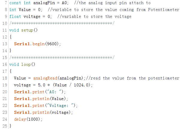
1) Define the variable
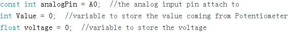
Here we define not only one pin, but also two more variables which will be used later.
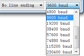
Set the serial communication rate in setup().
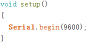
Since the rate is 9600 by default after the serial monitor is opened, we define it as 9600. Certainly, you can set any in the drop-down list as you want.
2) Read the value of A0 in loop() and print it in Serial Monitor.
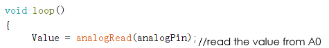
Read value from analogPin(A0) and store the value in the variable Value.
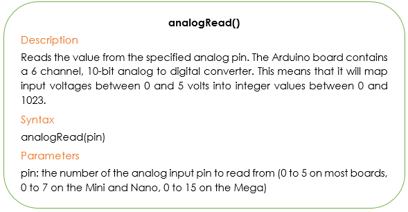
Then convert the value read into a voltage value. Previously we map 0-5V to 0-1023, but here to know the voltage, we need to convert it inversely.
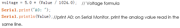
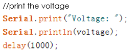
Serial.print(): Call the print() function in library Serial, and then print the data to the serial monitor.
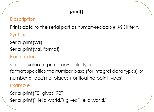
The function of println() remains almost the same with print() which contains newline(\n). You will see the digital value (as 1023 below) reveals in the newline.
The complete code is as follows:
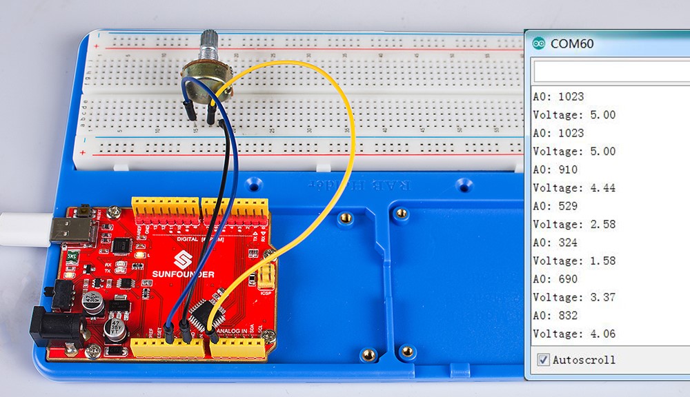
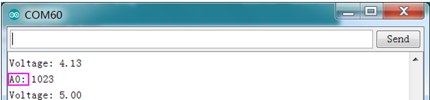
Step 3: After finishing the code, remember to save it. Then upload the code to the board. You will see the voltage and A0 value in Serial Monitor.
Note: Though the GND connected in the figure below may be different from as shown in the schematic diagram above, each ground is connected in the circuit. So you can just connect to the GND as labeled.