Introduction
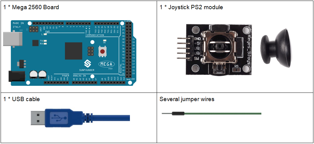
A joystick is an input device consisting of a stick that pivots on a base and reports its angle or direction to the device it is controlling. Joysticks are often used to control video games and robots. A Joystick PS2 is used here.
Components

Experimental Principle
This module has two analog outputs (corresponding to X,Y biaxial offsets) and one digital output representing whether it is pressed on Z axis. The module integrates power indicator and can display operation condition.
In this experiment, we use the Mega 2560 board to detect the moving direction of the Joystick knob and pressing of the button.
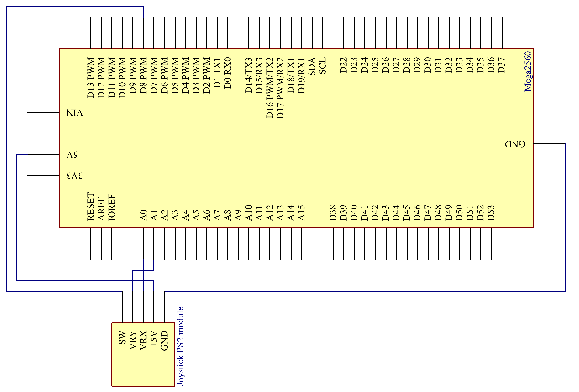
The schematic diagram:

Experimental Procedures
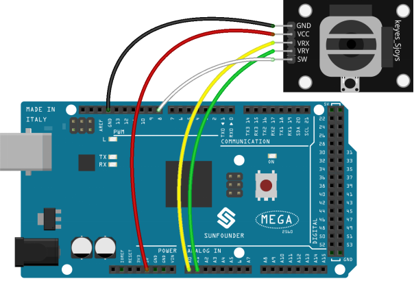
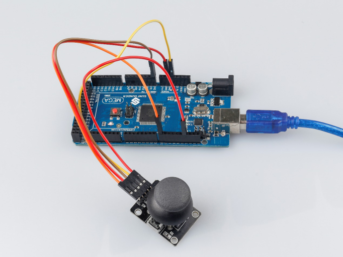
Step 1: Build the circuit

Step 2: Open the code file.
Step 3: Select the Board and Port.
Step 4: Upload the sketch to the board.
Now, push the rocker and the coordinates of X and Y axes displayed on Serial Monitor will change accordingly; press the button, and the coordinate of Z=0 will also be displayed.

Code Analysis
The code is use the Serial monitor to print the value of the VRX,VRY and SW pins of the joystick ps2.
const int xPin = A0;                    //the VRX attach to
const int yPin = A1;                    //the VRY attach to
const int swPin = 8;                    //the SW attach to

void setup()
{
  pinMode(swPin, INPUT);                //set the SW pin to INPUT
  digitalWrite(swPin, HIGH);            //And initial value is HIGH
  Serial.begin(9600);
}

void loop()
{
  Serial.print("X: ");
  Serial.print(analogRead(xPin), DEC);  // print the value of VRX in DEC
  Serial.print("|Y: ");
  Serial.print(analogRead(yPin), DEC);  // print the value of VRX in DEC
  Serial.print("|Z: ");
  Serial.println(digitalRead(swPin));   // print the value of SW
  delay(500);
}