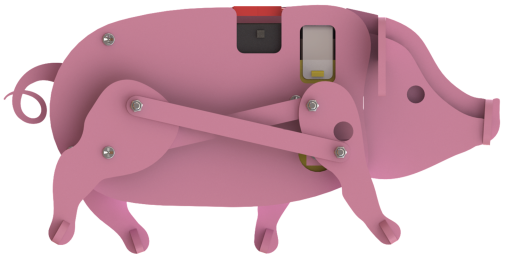
The right leg
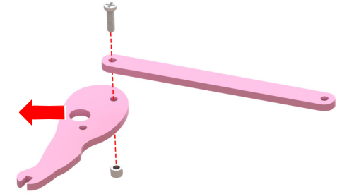
Face the 11th board to the arrow side to insert M3*8 screw from the hole of 17th board and the leg, then fix M3 self-lock nut and M3 screw by socket. Note: Do as shown in the picture, or else mistakes may occur.
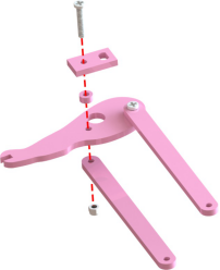
Insert the hole of board 9,7,17 and 11 by M3*12 screw, then fix M3 nut and M3 screw with the help of socket.
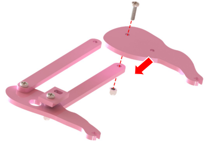
Face board 16 to the arrow direction and fix with board 11 by M3 nut and M3*8 screw.
The left leg
Face the board 11 to the arrow direction and insert M3*8 screw into the hole of board 11 and 17, then fix M3 self-lock nut and M3 screw with the help of socket. Note: not to assemble on reverse direction.
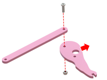
Insert board of 9, 7, 17 and 11 by M3*12 screw and fix M3 nut and M3 screw by socket.
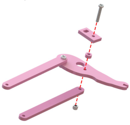
Face the board of 16 to the arrow direction as shown below and fix with board 11by M3 nut and M3*8 screw.
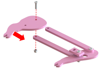
The rightside
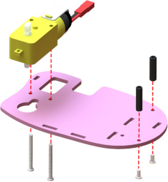
Insert the motor into board 2, then insert two M3*28 screw into motor and board 2, then fix M3*6 screw and M3*20 bi-pass plastic standoff at the other two holes.
Put motor shaft on three board 6 and put the motor shaft on the right leg of board 9. Rotate 17th board to let it be in the center of the motor, then fasten M2*4 screw into the hole by screw driver.
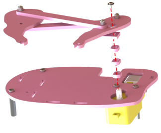
Insert M3*16 screw into16th board and 11th board, M3*6 bi-pass plastic standoff and 2nd board to fasten by M3 nut on the other side.
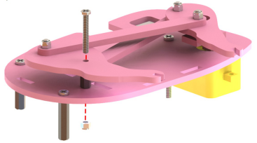
Keep flat of 2nd board, then insert 12th, 13th and two 10th board.
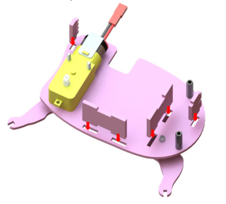
The leftside
Insert the M3*16 screw into 16th, 11th board on the left leg, and also M3*6 bi-pass plastic standoff and 1st board to fasten with M3 Nut on the other side.
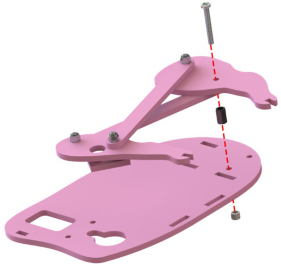
Overlap the other side of motor with the left inner board, note to insert all the boards at the last step to insert into the 1st board, and insert the M3*28 screw into round hole of 1st board, then fix two M3*20 bi-pass plastic standoff by M3*6 screw.
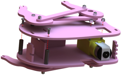
Put three 6th boards into the motor shaft and also for 9th board on the left leg, then rotate 17th board until it is aligning with center of motor, then fasten with M2*4 screw into the center of the motor shaft by screw driver. Note: The 9th board on the left should be in reverse side of rightone.

Assemble Head andFeet
Insert the 4th board into 13th board.
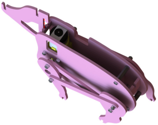
Insert two 3rd board into the gap of 13th board.
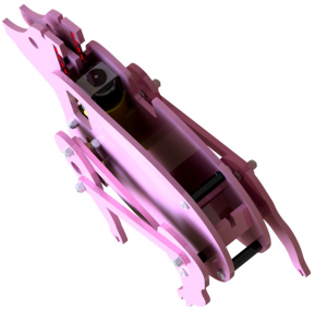
Insert 5th board into the gap between 3rd and 4th, then insert 14th board into the gap before 4th board.
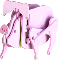
Insert 15th board into the gap of 12th, then insert four 8th board into the gap under 16th and 17th.
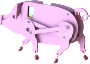
CircuitConnection
Insert four 5th battery (not included) into battery holder and put back the cover. Insert the battery holder into the two 10th boards.
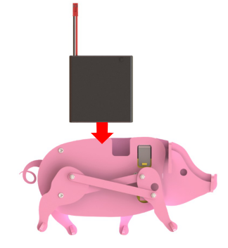
Connect red and black line of motor with the battery holder.
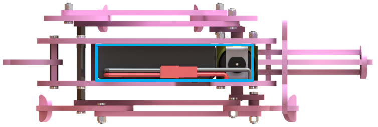
Put the pig in flat place and slide the power switch, then it can walk.
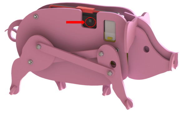
Notes:
- For a better experience, place it in a frictionless surface to walk.
- Screw and self-lock nut should not be too tight, or else, the pig cannot walk smoothly; also, unsteady structure and toe out of the four limbs if too loose. Both of them will increase motor load and lead to battery power faster.
- The front leg can be rotated to the location as shown below. If the legs are in other place, the pig may cannot stand still, but wouldn’t interrupt the normal work.
