Introduction
In this lesson, let’s try something interesting – gradually changing the luminance of an LED through programming. Since the pulsing light looks like breathing, we give it a magical name – breathing LED. We’ll accomplish this effect with pulse width modulation (PWM).
Components
– 1 * SunFounder Uno board
– 1 * Breadboard
– 1 * LED
– 1 * Resistor (220Ω)
– 1 * USB cable
– Jumper wires
Principle
PWM
Pulse width modulation, or PWM, is a technique for getting analog results with digital means. Digital control is used to create a square wave, a signal switched between on and off. This on-off pattern can simulate voltages in between full on (5 Volts) and off (0 Volts) by changing the portion of the time the signal spends on versus the time that the signal spends off. The duration of “on time” is called pulse width. To get varying analog values, you change, or modulate, that width. If you repeat this on-off pattern fast enough with some device, an LED for example, it would be like this: the signal is a steady voltage between 0 and 5V controlling the brightness of the LED. (See the PWM description on the official website of Arduino).
In the graphic below, the green lines represent a regular time period. This duration or period is the inverse of the PWM frequency. In other words, with Arduino’s PWM frequency at about 500Hz, the green lines would measure 2 milliseconds each.
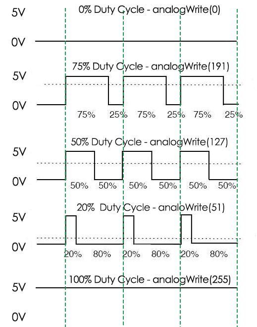
A call to analogWrite() is on a scale of 0 – 255, such that analogWrite(255) requests a 100% duty cycle (always on), and analogWrite(127) is a 50% duty cycle (on half the time) for example.
You will find that the smaller the PWM value is, the smaller the value will be after being converted into voltage. Then the LED becomes dimmer accordingly. Therefore, we can control the brightness of the LED by controlling the PWM value.
The schematic diagram
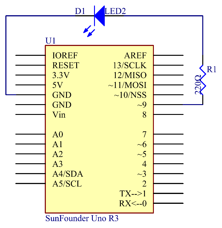
Principle: By programming, we can use the analogWrite() function to write different values to pin 9. The luminance of the LED will change based on that. On the SunFounder Uno board, pin 3, 5, 6, 9, 10, and 11 are the pins of PWM (with “~“ marked). You can connect any of these pins.
Experimental Procedure
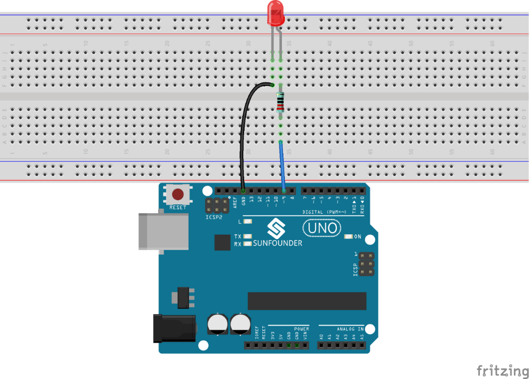
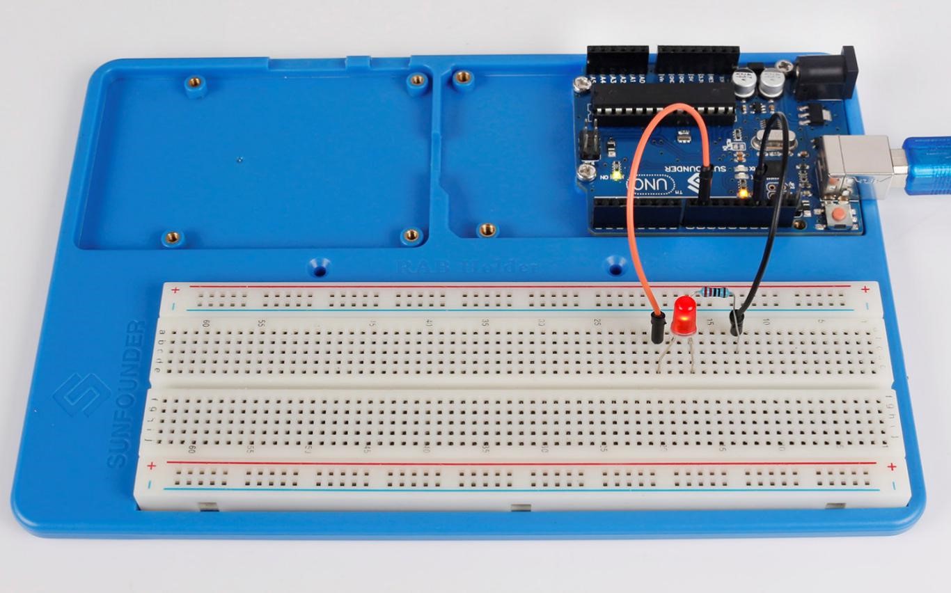
Step 1: Build the circuit
Step 2: Open the code file
Step 3: Select correct Board and Port
Step 4: Upload the sketch to the SunFounder Uno board
Here you should see the LED gets brighter and brighter, then slowly dimmer, and again brighter and dimmer repeatedly, just like breathing.
Code
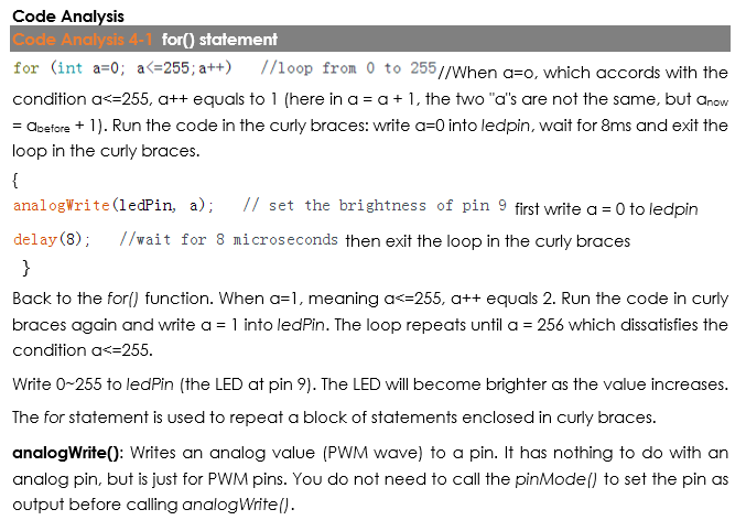
| //Controlling LED By PWM //The led the LED lights up gradually,and then goes out gradually,repeatedly //Email:support@sunfounder.com //Website:www.sunfounder.com //2015.5.7 /**************************************************************/ const int ledPin = 9; // the pin that the LED is attached to void setup () { pinMode(ledPin,OUTPUT); } void loop() { for (int a=0; a<=255;a++) //loop from 0 to 255 { analogWrite(ledPin, a); // set the brightness of pin 9: delay(8); //wait for 8 microseconds } for (int a=255; a>=0;a–) //loop from 255 down to 0 { analogWrite(ledPin, a); // set the brightness of pin 9: delay(8); //wait for 8 microseconds } delay(800); //wait for 800 microseconds } |