Introduction
A joystick is an input device consisting of a stick that pivots on a base and reports its angle or direction to the device it is controlling. Joysticks are often used to control video games and robots. A Joystick PS2 is used here.
Components
– 1 * SunFounder Uno board
– 1 * USB data cable
– 1 * Joystick PS2 module
– Several jumper wires
Experimental Principle
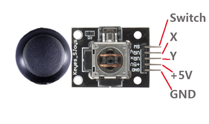
This module has two analog outputs (corresponding to X,Y biaxial offsets) and one digital output representing whether it is pressed on Z axis. The module integrates power indicator and can display operation condition.
In this experiment, we use the SunFounder Uno board to detect the moving direction of the Joystick knob and pressing of the button.
Experimental Procedures
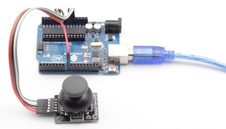
Step 1: Build the circuit
Joystick PS2 Module SunFounder Uno
SW ————————————– D8
VRx ————————————- A0
VRy ————————————- A1
+5V ————————————- 5V
GND ———————————— GND
Step 2: Program (Please refer to the example code in LEARN -> Get Tutorial on our website)
Step 3: Compile
Step 4: Upload the sketch to SunFounder Uno
Now, push the rocker and the coordinates of X and Y axes displayed on Serial Monitor will change accordingly; press the button, and the coordinate of Z=0 will also be displayed.
Code
| const int xPin = A0; const int yPin = A1; const int swPin = 8;void setup() { pinMode(swPin,INPUT); digitalWrite(swPin, HIGH); Serial.begin(9600); }void loop() { Serial.print(“X: “); Serial.print(analogRead(xPin),DEC); Serial.print(“|Y: “); Serial.print(analogRead(yPin),DEC); Serial.print(“|Z: “); Serial.println(digitalRead(swPin)); delay(500); } |