Introduction
In our lives, is the touch table lamp visible everywhere convenient and interesting? In this lesson, we will make a simple touch lamp with simple resistors and LEDs.
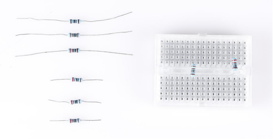
Components
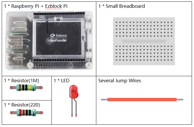
![]() Circuit
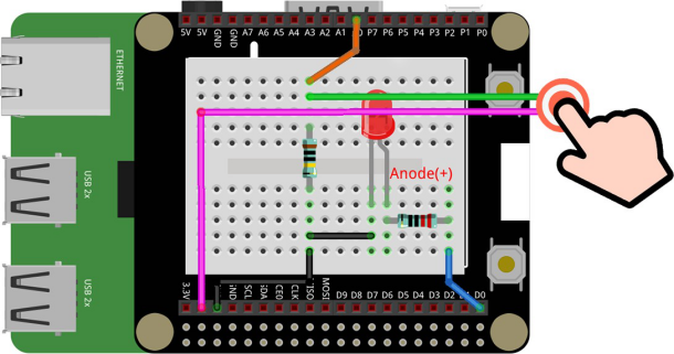
Circuit
Get the circuit connected according to the picture. Two wires are drawn from the A0 pin and the 3.3v pin respectively. The human body is equivalent to a resistor being connected to the circuit to play the role of voltage divider.
Programming Steps
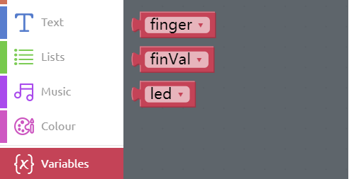
Step 1
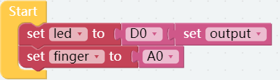
Click Create variable button to create the three variables: finger, finVal and led.
Step 2
Drag two set to blocks from the Variables category to the Start block, then put D0 and A0 from the Raspberry Pi category to the area behind them respectively. And set the D0 pin to output mode.
Step 3
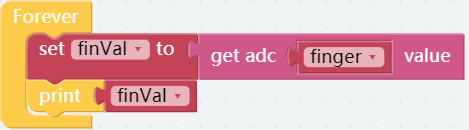
Get a set finVal to block from the Variables category and put it into Forever block followed by the get adc P0 value block that is from the Raspberry Pi category. Finally put the finger block of the Variables category into the proper position as shown.

Step 4
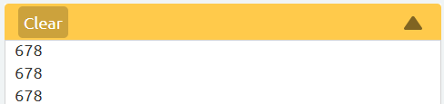
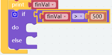
At this time, we can first print the touch value on the Debug Monitor with the print block. Flash the code into the control board, then see the touch values on the Debug Monitor when the finger leaves or touches the 2 wires.
Step 5
The figures below are the values appearing after finger touch, so the critical value can be set to 500.
Step 6
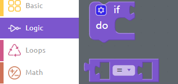
Drag an if do block from the Logic block into the circuit. Then put a Comparison Operator (=) block behind the if block.
Step 7
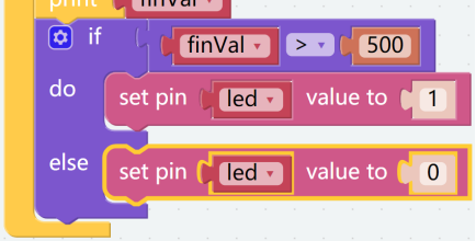
Place the finVal block and the number block properly to create the judgement condition. When the value of finVal is greater than 500, it indicates that the finger touch is completed and it is time to perform the next step.
Step 8
Thereafter, set pin led value to 1 to let the LED light up.

Step 9
Turn off the LED without touching it with your finger.
Step 10
Save the project and flash it into the Raspberry Pi (refer to lesson 0 for details). When we touch two wires at the same time with our fingers, the light is on. Otherwise the light is out.
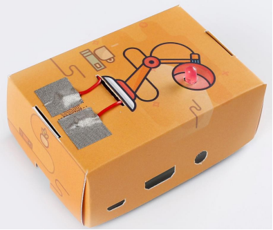
Fold Cardboard
To better apply this kit, we have set fun courses from the shallower to the deeper, as well as the cardboard for the advanced section of the course. Next, we need to fold the cardboard by ourselves, from which we will experience the fun of operation.

Step 1
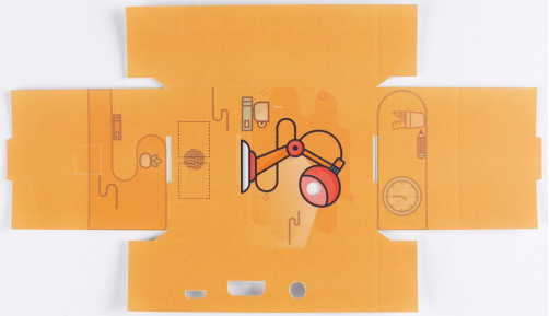
Take out the matching cardboard.
Step 2
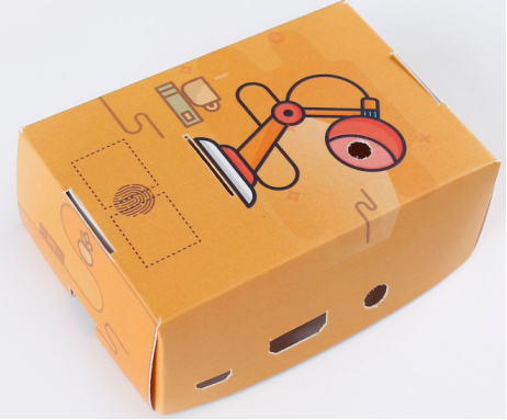
Fold a cube like this, according to the creases.
Step 3
For the sake of beauty, the pin of the resistance in the physical picture is manually shortened. You can choose whether to cut the resistor pin as you prefer.
Step 4
Build the circuit on the Raspberry Pi according to the previous circuit diagram. Please do NOT change the position of components optionally when building circuits, in case the card cannot be installed.

Step 5
Find the conductive tape and two wires. Cut 4 pieces of 15x15mm coductive tape, Then wrap one end of each wire with a piece of tape to increase the contact area of the wire.

Step 6
Connect the two wires as shown below (see previous circuit diagram).

Step 7
Use the conductive tapes to stick the wires to the area of cardboard as shown in the figure, and Install the cardboard on the Raspberry Pi.