Introduction
Have you ever experienced an exciting racing scene? In this lesson, we will use the board to simulate a racing scene. After the countdown stops, the buzzer will sound and the race flag will wave to indicate that the race begins.
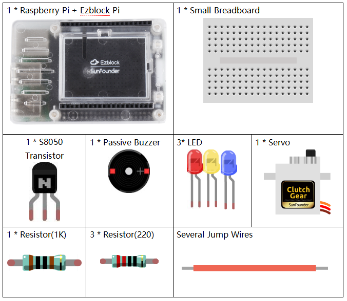
Component
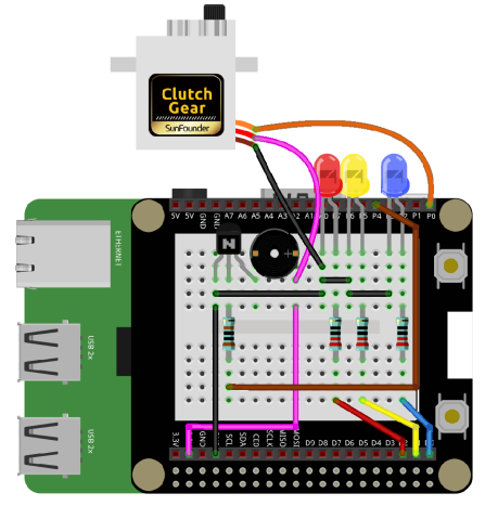
Circuit
In this lesson, we use many components, including a LED working as a countdown indicator, a buzzer working as an alarm, a servo working as a waving flag, some resistances and so on. Connect LEDs to D0, D1, D2; the buzzer to P4; the servo to P0.
Programming Steps
Step 1
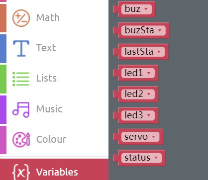
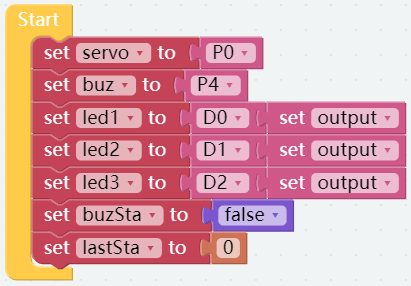
After creating the project, click Variables category to create 8 variables: servo, buz, led1, led2, led3, buzSta, status and lastSta.
Step 2
Initialize the variables as shown below.
Step 3
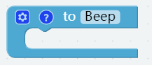
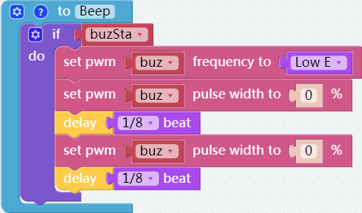
Create a function named Beep to control the buzzer.
Step 4
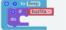
Drag an if do block into the Beep block, and place a buzSta block behind the if block.
Step 5
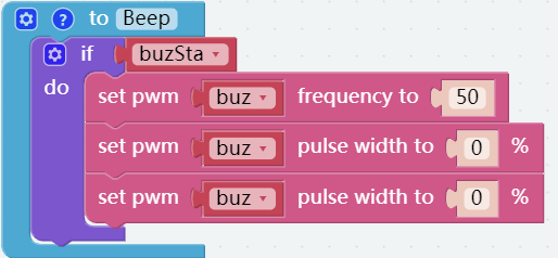
Drag a set pwm P0 frequency to block and two set pwm P0 pulse width to 0% blocks into do block and place the buz block in the slot of pin.
Step 6
Use 2 delay blocks to set the beats to 1/8 and add a Low C block to the set pwm buz frefuency to block. Change the value to Low E, and you can hear the buzzer sounding MI in a beat of 1/8.
Step 7
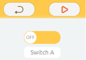
Go to the Remote Control page and drag a Switch to the right area.
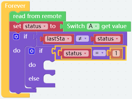
Step 8
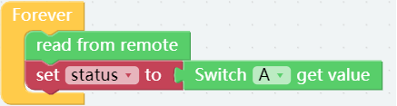
Go back to the Programming page, drag the read from remote block from Remote category into Forever block, and then assign the value of switch A to variable, status. as shown below.
Step 9
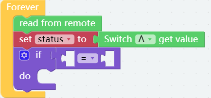
Drag an if do block from the Logic category then put it below set status to block, and place a Comparison Operator ( = ) block behind it.
Step 10
Change the equal sign into inequality sign, then place the lastSta block on the left of it and the status block on the right.

Step 11
Drag another if do else block to place in do, followed by a Comparison Operator ( = ) block with a status block on the left and a number block 1 (change 0 to 1) on the right.
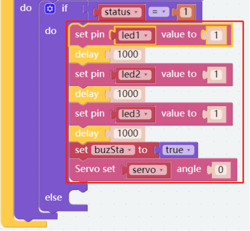
Step 12
Light up the LED 1, LED 2 and LED 3 with an interval of 1s, then set the state of the variable, buzSta to “true” and let the rocker arm of the servo turn to a certain angle as shown below.
Step 13
In the else, set buzSta to false, then set the corresponding values to turn off the three LEDs and set the servo angle to 90.

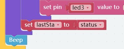
Step 14
Here, you need to assign the value of the variable, status to lastSta. Besides, you should place a Beep block below the first if do block.
Step 15
Save the project and flash it into the Raspberry Pi (refer to lesson 0 for details).
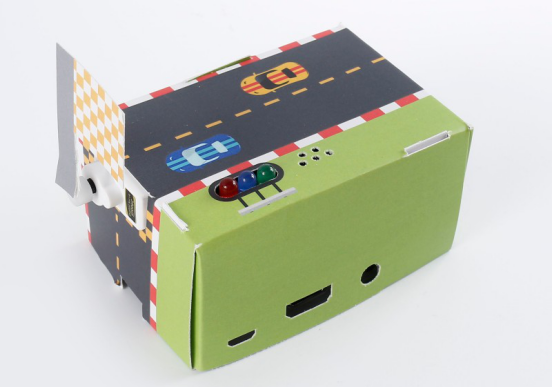
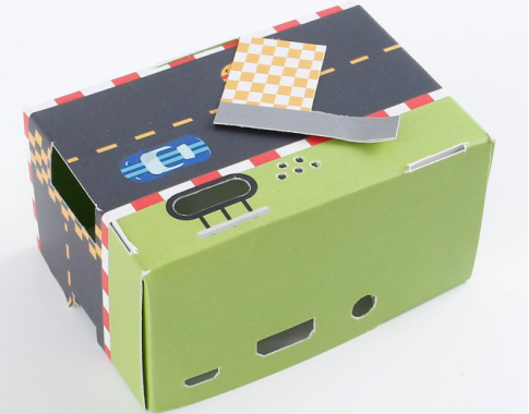
Fold Cardboard
Step 1
Take out the matching cardboard of lesson 10.
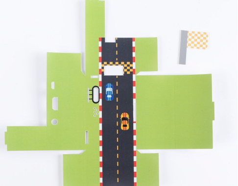
Step 2
Fold a cube like this, according to the creases.
Step 3
Build the circuit according to the picture below. Please do NOT change the position of components optionally when building circuits, in case the card cannot be installed. You also need to stick the servo to the case with double-sided tape.
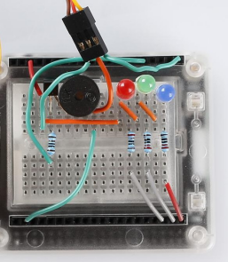
Step 4
Assemble the cube of cardboard and the circuit as shown.