Introduction
In this lesson, we are going to make a smart alarm clock. Leave it by your window, and when the first light of the morning comes in, it will ring to wake you up.
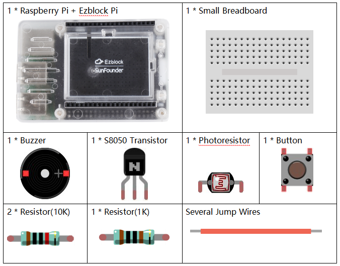
Components
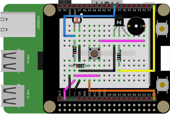
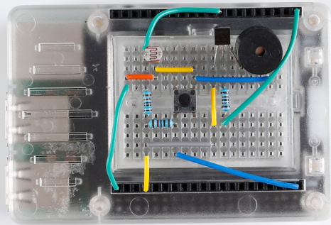
Circuit
The photoresistor can change its resistance value with the intensity of the light. The stronger the light is, the smaller the resistance value will be. When the intensity of the light reaches a certain degree, the buzzer sounds.
Programming Steps
Step 1
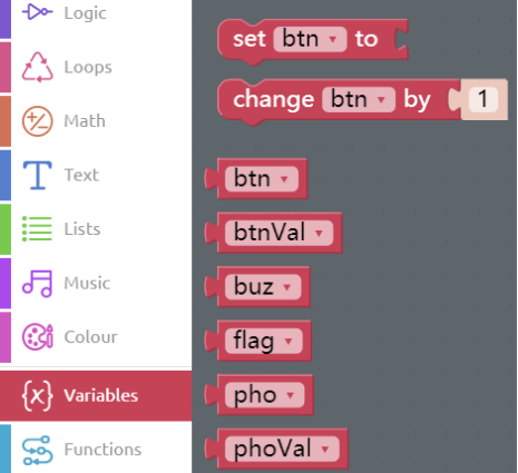
After creating the project, click Create variable button to create 6 variables: btn, btnVal, buz, flag, pho, and phoVal respectively.
Step 2
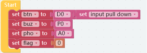
Assign the values of pins to each variable at the beginning. The button is connected to D0 and we set it into input pull down. And we initialize the value of the flag to 0.
Step 3
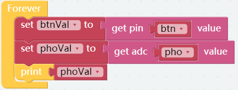
The values of btn (button) and pho (photoresistor) are assigned to btnVal and the
phoVal variable respectively.

Step 4
A print block is put below the set phoVal to block to help print the photoresistor’ s value.
Step 5
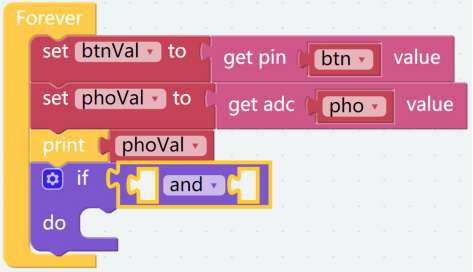
Drag an if do block and an and block into the Forever block.
Step 6
Create two judgement conditions. Drag 2 Comparison Operator ( = ) blocks from the Logic category to the and block. Furthermore, change values as follows. When the conditions on both sides of and are met, code in do is executed.

Step 7
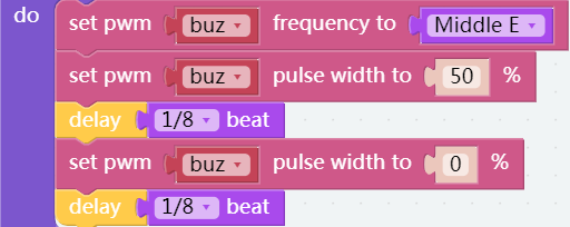
Put a set pwm P0 frequency to block and two set pwm P0 pulse width to 0% blocks into the do block, then place 3 buz blocks into the the slot of pins.

![]() Step 8
Step 8
Drag the Low C block from the Music category to the set pwm P0 frequency toblock, then add 2 delay blocks to set the beats to 1/8.
Step 9
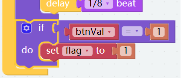
Add another if do block below the if do block to create another judgment condition that if the button is pressed, set flag to 1, then the system will not enter the first if do block again, and the buzzer will not ring.
Step 10
Save the project and flash it into the Raspberry Pi (refer to lesson 0 for details). We can simulate a night environment by blocking the light from the photoresistor by hand to test whether the circuit works well.
Fold Cardboard
Step 1
Take out the matching cardboard of lesson 5.

Step 2
Fold a cube like this, according to the creases.

Step 3
Build the circuit as follows. Please DO NOT change the position of components optionally when building circuits, in case the card cannot be installed.
Step 4
Mount the cube of cardboard on the circuit as shown.
