Introduction
A0~A7 are analog pins used to output analog values of 0-4095 and P0-P7 are used to output PWM signal. In this lesson, let’s learn how to use these types of pins. The potentiometer is connected to an analog pin and the LED is connected to a PWM pin; the brightness of LED will be changed by the potentiometer. At the same time you can see the analog value of the potentiometer on the debug monitor.
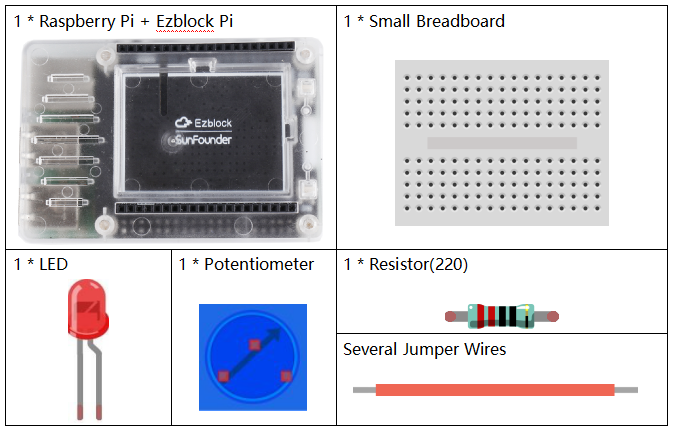
Components
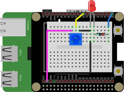
Circuit
Connected to a 220 ohm resistor, the LED is attached to P0. And connect the middle pin of the potentiometer to A0. When you turn the knob of the potentiometer, the resistance value will change and the LED will turn on or off by your changes.
Programming Steps
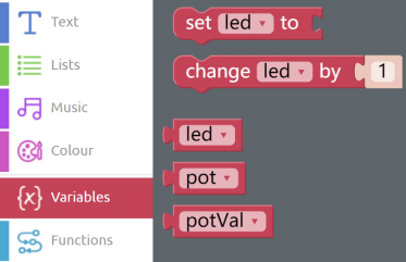
Step 1
Click Create variable button, and you can create three variables named led, pot and potVal.
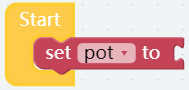
Step 2
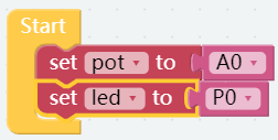
Click into the Variables category, then drag the set pot to block into the Start block and change led to pot.
Step 3
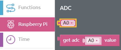
Find the A0 block in the ADC subclass of the Raspberry Pi category and put it behind the set pot to block.
Step 4
Long press the set pot to block to duplicate a same block. Then replace the A0 block with the P0 block under the PWM subclass of the Raspberry Pi.
Step 5
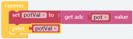
Put a set led to block into the Forever block, and change the pot into potVal.

Step 6
Find the get adc A0 value block in Raspberry Pi category, then put it behind the set potVal to block. Moreover, put the pot block into the slot of pin. This step is to read the value of the potentiometer and assign it to the variable potVal.

Step 7
Take out the print block from the Basic category and put it under the set potVal to block, then connect a potVal so as to print the value of potentiometer.
Step 8
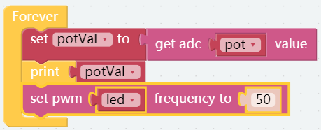
Click the Raspberry Pi category, find the set pwm frequency to block under PWM subclass and put it below the print block. Then put a led block in the the slot of pin. This step is used to set the pin led frequency to 50hz.
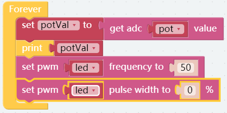
![]() Step 9
Step 9
Similarly, find the set pwm pulse width to 0% block under PWM subclass and drag it into the Forever block in order to define the duty cycle of the pin led.
Step 10
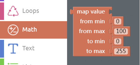
Since the potentiometer value ranges 0-4095 and the duty cycle ranges 0-100, a map function is required to map 0-4095 to 0-100, as shown below. And you need to drag the map block from the Math category into the pulse width block.
Step 11
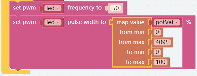
Then add a potVal block and change the value as below.
Step 12
Save the project, then flash it to the Raspberry Pi (refer to the lesson 0 for details). Then turn the knob of the potentiometer to see that the brightness of the LED also changes.