Introduction
In this lesson, we use the line follower sensor module on the car to detect the black line on the road and obtain the corresponding analog value. The principle is that infrared rays have different reflection intensities on surfaces in different colors. We’ll also apply the sensor in the following projects.
Note: It doesn’t have to be a black line, just something that contrasts well with the surface color.
Programming Steps
Step 1
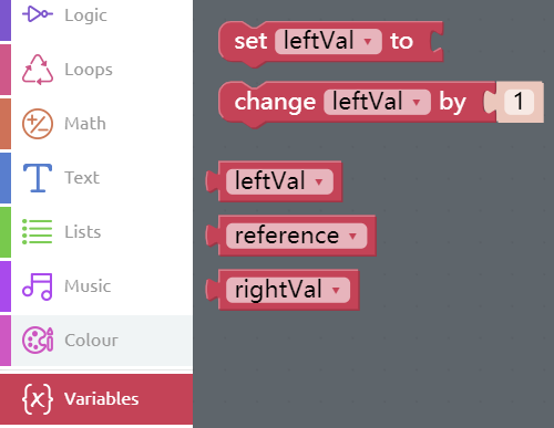
Click the Create variable button in the Variables category to create 3 variables called leftVal, reference and rightVal.
Step 2
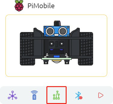
Click the Simulation icon on the left of the page to enter the Simulation page.
Step 3
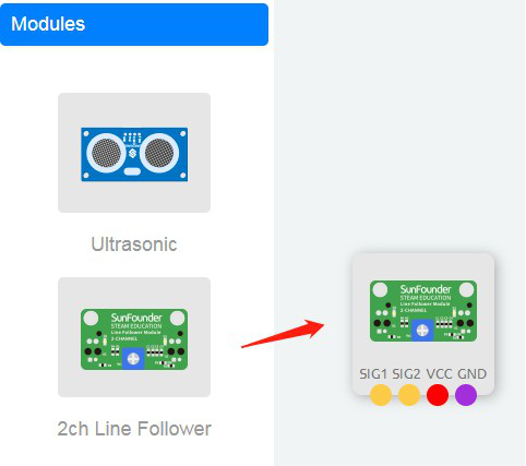
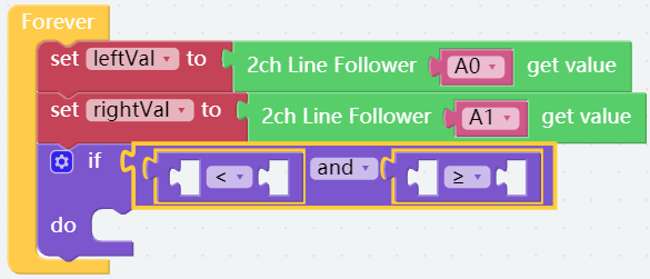
In the left module category, drag the 2ch Line Follower module to the right area.
Step 4
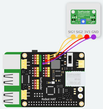
Connect SIG1 of 2ch Line Follower module to A1 port, SIG2 to A0 port, and then connect 3V3 and GND to 3.3V and GND of Robot HAT.
Step 5
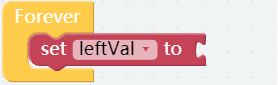
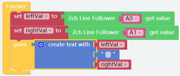
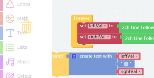
Click Variables category and drag the set leftVal to block into Forever block.
Step 6
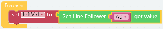
Click Modules category and drag 2ch line follower A0 to get value block to the area behind set leftVal to block. Let the read value of the left line follower sensor be assigned to leftVal variable.
Step 7
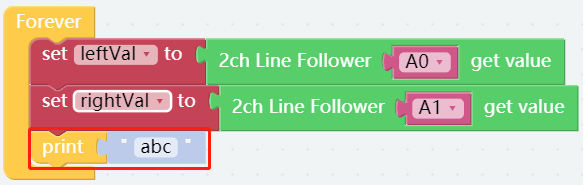
In the same way, assign read value of the right line follower sensor to the rightVal variable.
Note: The so called left and right are recognized by your confronting the tail of car.

Step 8
At this stage, we can try to print out the reading value of the sensor. Click on Basic category and drag a print block into Forever block.
Step 9
Click Text category, then drag a create text with block to the right of print block.
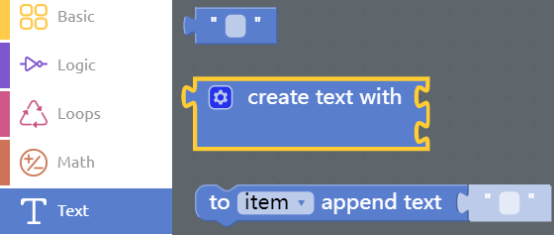
Step 10
After that, click setting icon in the upper left corner, and add one more item to the join block.

Step 11
Place the leftVal block and rightVal block from the Variables category into the create text with block. The second place is embedded with the Text block in Text category (blank block), and we input a space.
Step 12
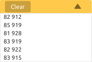
Connect the Bluetooth then click Flash to compile and download the code. Then put the left line follower sensor in the black line and the right one in the white area, you can get the read values of the sensor as show below. So we can set the reference as 500.
Step 13
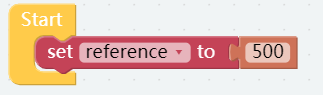
Place a set reference to block from Variables category into Start block. Next, add a number 0 block on the right, changing the value into 500.
Step 14
Print block will slow down the program, so let’s remove print block from the code. Drag print block to the category area to delete the block.
Step 15
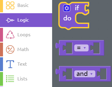
Drag one if do block, one and block and two Comparison Operator ( = ) block from Logic category to the area below the set rightVal to block.
Step 16
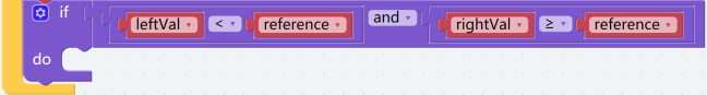
The combined block is as shown below. Remember to change the two equal signs to the less than sign and greater than sign respectively.
Step 17
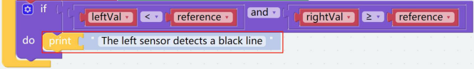
Place 1 leftVal, 1 rightVal and 2 reference block into the combined block as shown below. It is meaning that the left sensor detects a black line.
Step 18
Click into Basic category, then drag print block into if do block, clicking “abc” and inputting “The left sensor detects a black line”.
Step 19
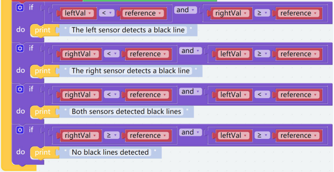
Long press the if do block and then click Duplicate to copy other 3 same combined blocks.

Step 20
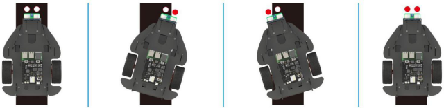
Modify the parameters as shown below.
Step 21
Save the project and flash it into the Raspberry Pi (refer to lesson 0 for details). Moreover, keep car sensor in the four situations above to test whether it works well.