Introduction
In this lesson, let’s learn how to use the IoT function on the App to simulate a smart home. The functions of reading the value of the sensor and controlling the state of the object can be realized through the IoT Control page on the APP.
Components
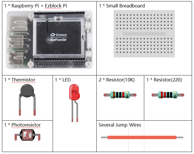
![]() Circuit
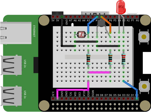
Circuit
Connect the photoresistor and thermistor to A0 and A1 respectively, and connect a LED to D0. On the IoT page of the APP, the changes of data in the environment can be read in real time, and the light can be controlled remotely.
Programming Steps
Step 1
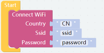
In order to experience IoT function, we need to use Connect WiFi block under the Raspberry Pi category.
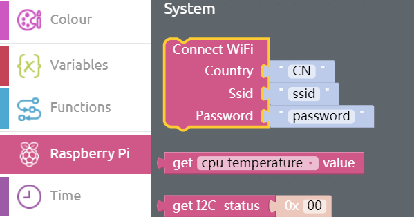
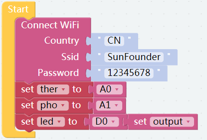
Connect WiFi block is required to put in the Start block. And behind the Country, you need to input the Abbreviation of the country; similarly, input the name of WiFi behind the Ssid and the code of WiFi to the right of Password.
Step 2
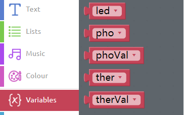
Click on Create variable to create 5 variables: led, pho, phoVal, ther and therVal.
Step 3
Initialize the 3 variables.
Step 4
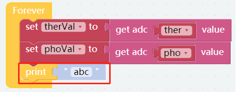
In the Basic category, drag a print block to below the set phoVal to block.
Step 6
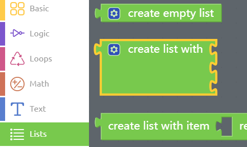
Drag a create list with block from the Lists category into the print block.
Step 7
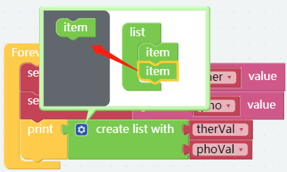
Since we only need to print two variables, cancel an item by dragging it to the left area. Then put therVal block and phoVal block behind the create list with block, which is used to print the values of the thermistor and the photoresistor in the form of list.
Step 8
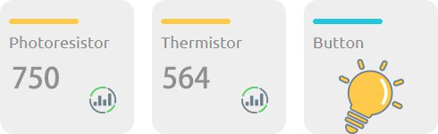
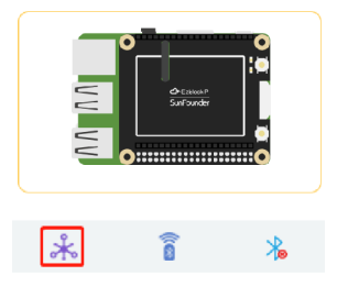
Click the IoT Control icon to lead into IoT Control page.
Step 9
Click the button + to add sensors/actuators.

Step 10
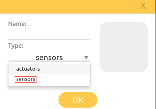
Click on the triangle as shown. Here, we select “sensors”.
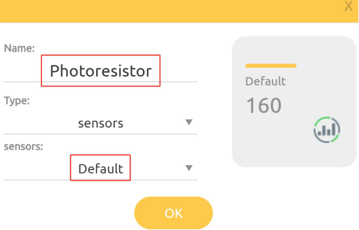
Step 11
Next, select “Default” and input the name, Photoresistor.
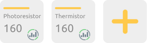
Step 12
Follow the same method to create a Thermistor to monitor the value of the thermistor.
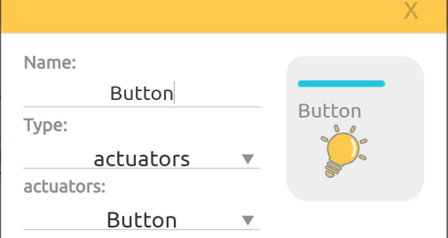
Step 13
Select the appropriate options as shown below.
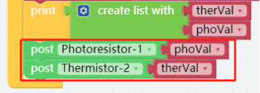
Step 14
When you go back to the Programming page, you will see an additional IoT category. Then place 2 post blocks that are in the IoT category below the print block, change the value, and add corresponding blocks as shown below.
Step 15
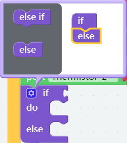
Place an if do block below the post block. And click the setting button in the top left corner; drag an else block to below the if block.
Step 16
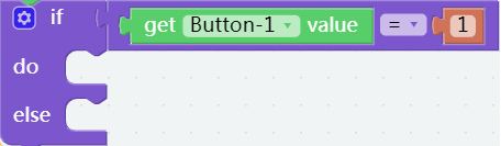
In the Logic category, find a Comparison Operator ( = ) block and place it behind the if block, then get a get button-1 value block from the IoT category and a number 0 block (change 0 to 1); put them into the Comparison Operator ( = ) block.
Step 17
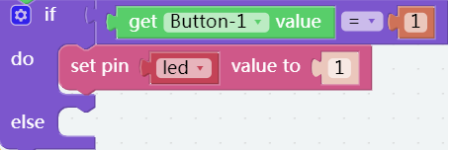
Place the set pin D0 value to block into the do, and put a led block in the the slot of pin, then set the value of led to 1. That is, if the button is detected to have been pressed, set the variable led to 1 to turn on the LED.
Step 18
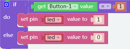
Otherwise, set the value of the variable, led to 0 to turn off the LED.
![]() Step 19
Step 19
Save the project and flash it into the Raspberry Pi (refer to lesson 0 for more details). Back to the simulation page, you will see that the values of photoresistor and thermistor change. When you press the Button, the LED will be on or off.