Are you excited when you open the box and see so many components? Keep your patience and take it easy. Please note that some details in the following steps need careful observation. You should double-check your work based on the figures in the manual after finishing each step. let’s start!
Front Wheels
Insert an M4x25 screw through a Flange Bearing (pay attention to the direction – the flange near the cap of the screw), a Steering Connector Plate, 3 Bearing Shields, 3 Hex Front Wheel Fixing Plates, and a front wheel, into an M4 Self-locking Nut as shown below:
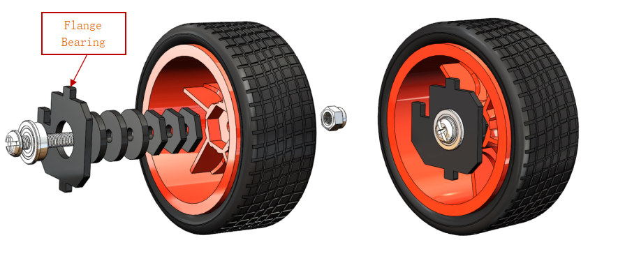
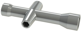
You can use the Cross Socket Wrench to secure the M4 Self-locking Nut, then use the screwdriver to tighten the M4x25 screw.
Note:
The Self-locking Nut should be screwed tight enough. It would be better to tighten the screw until the wheel and Steering Connector cannot move first, then loosen the screw a little, so that the Steering Plate can just move. Thus, the wheel can turn flexibly when the connection would not be too loose.
Assemble the other front wheel in the same way, but bear in mind the Steering Connector plate on the wheel should be symmetric with the previous one.
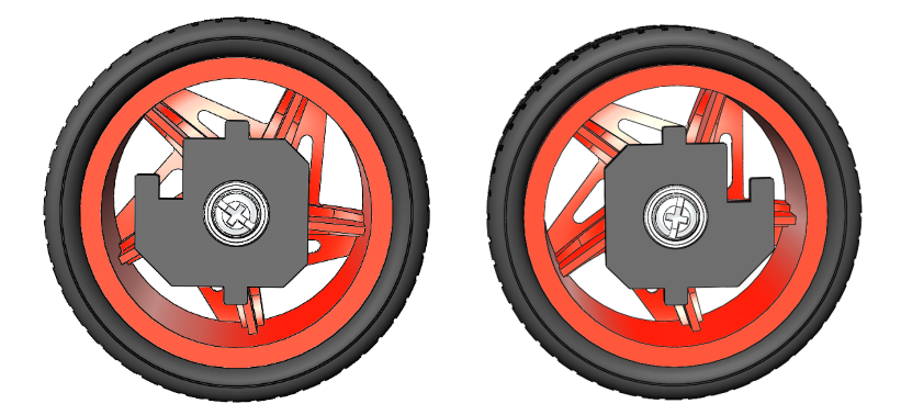
Now two front wheels have finished assembly.
Pan-and-Tilt
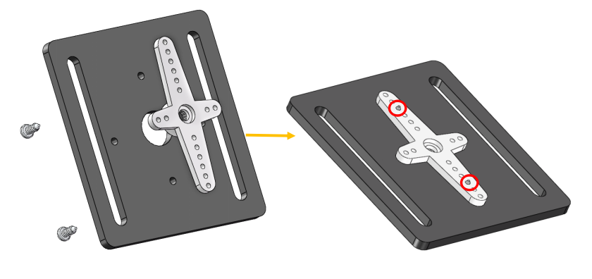
Take out the Cross rocker arm and mount it onto the Pan-and-tilt Base Plate with 2 M1.5x4 screws (into the hole like this). Pay attention to the holes on the round rocker arm to be fastened.
Do the same operation to the Camera Mount Plate
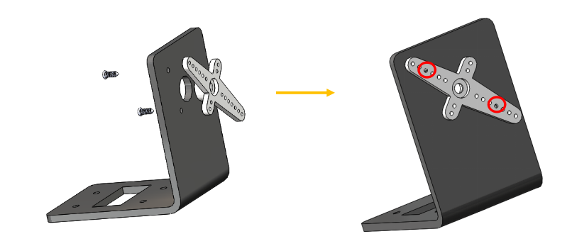
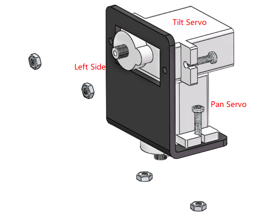
Assemble the two servos to the Pan-and-tilt Plate with four M2x8 screws and the M2 nuts (The 2 servo shaft are close to the left side ):
Steering Part
Connect the Steering Linkage and the 1-arm Rocker Arm with the M1.5×4 Self-tapping Screw (a longer one in the servo package).
Note: Insert it into the FIRST hole of the arm (as indicated by the arrow below) which is the farthest from the gears. Since the screw is larger than the hole, you should try to screw it hardly so as tight to the arm. Don’t worry of the arm which is soft.
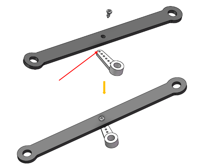
And also fasten them as tightly as possible, and then loosen the screw a little so the Steering Linkage can move flexibly.
Upper Plate
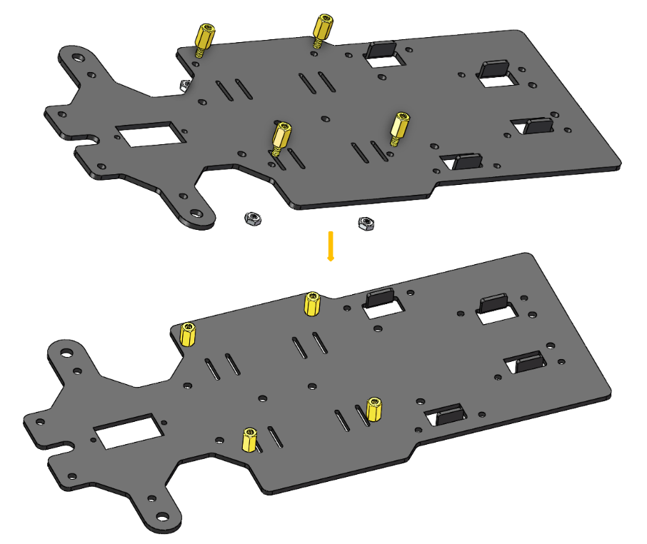
Mount the M2.5×8 copper standoffs and M2.5 nuts into the upper plate first. Pay attention that the side the protruding prop should face up.
Battery Holder
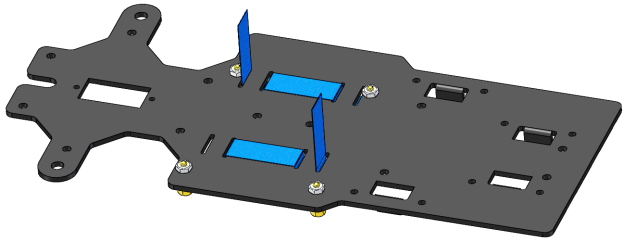
Turn the Upper Plate upside down. Cut the ribbon into two halves. Thread them through the holes on the plate. Pay attention to the direction and leave one end longer out of the plate for each to remove the battery easily later.
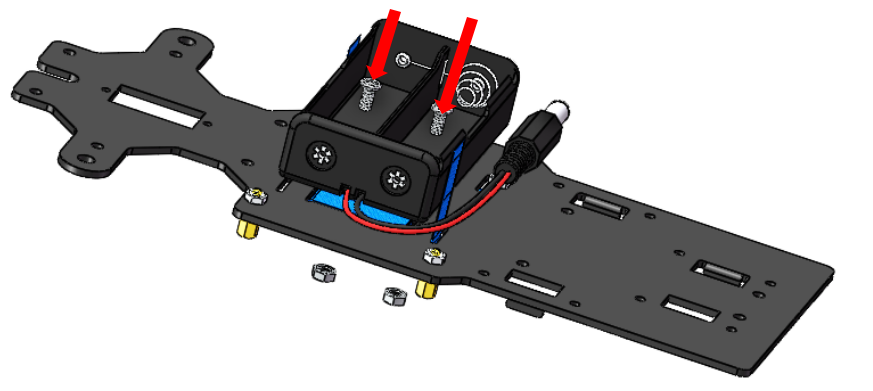
Fasten the battery holder with two M3x8 countersunk screws and M3 nuts. Pay attention to the direction of battery holder’s wire.
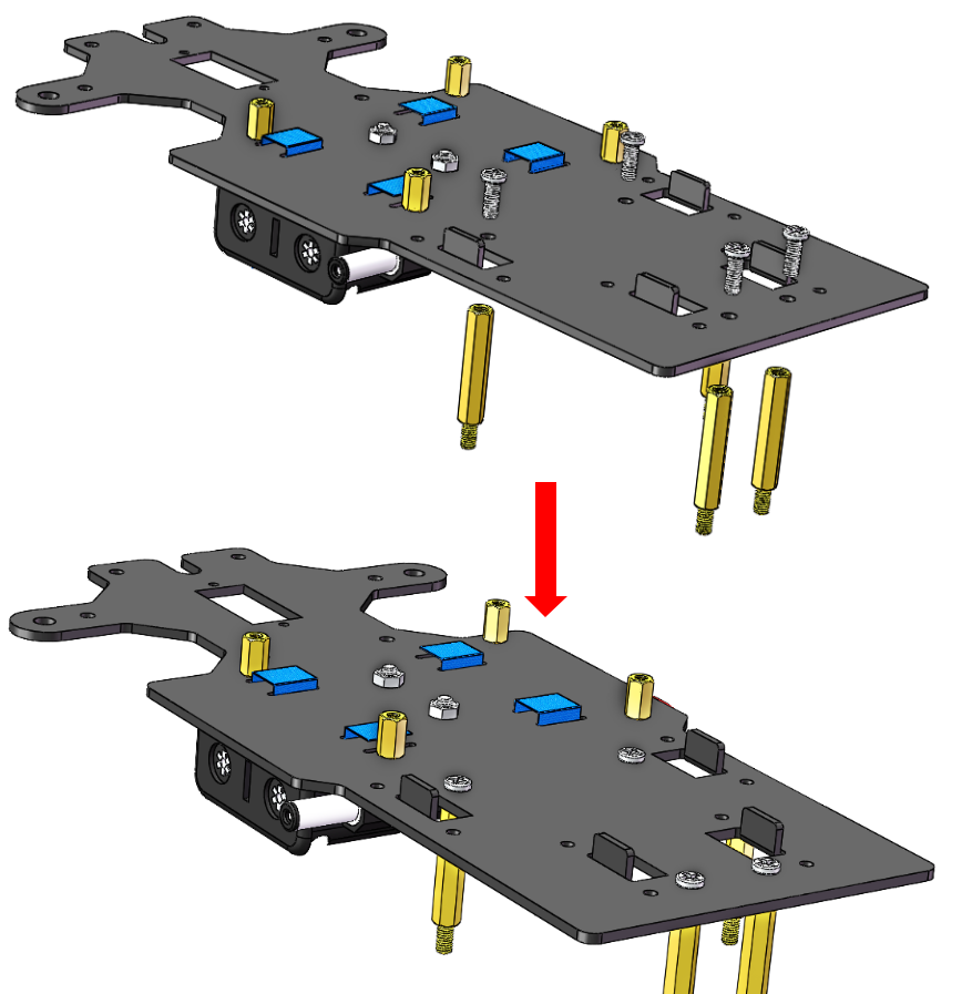
Rear Wheels (Screws)
Insert 4 M3x8 screws with four M3x25 copper standoffs:
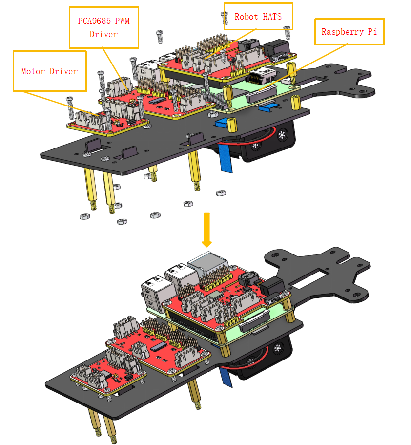
PCB Assembly
- Assemble the Raspberry Pi (TF Card inserted) with 8 M2.5×8 single pass copper standoffs, then plug the Robot HATS onto it.
2) Fix the Robot HATS with 4 M2.5×6 screws.
3) Fix The PCA9685 PWM Driver and the Motor Driver with 8 M2.5×12 screws and M2.5 nuts into the down plate:
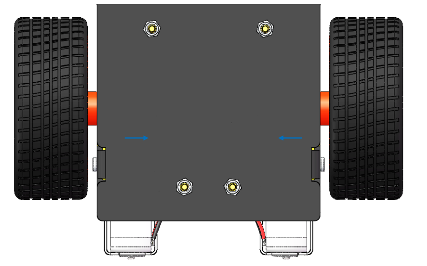
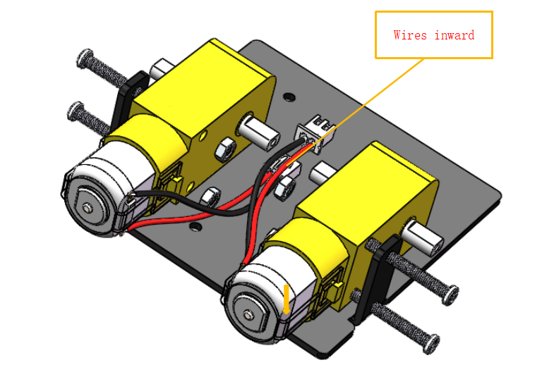
Fixing Rear Wheels
Assemble the two motors with four M3x25 screws and M3 nuts. Pay attention to place the motors with wires inward, providing convenience for connecting the circuit.
Assemble the rear wheels with 4 M3 nuts.
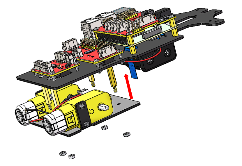
Align the rear wheels with the motor shaft, and rotate to insert them gently.