How to Operate on DeviceBit Platform
Register an Account on DeviceBit
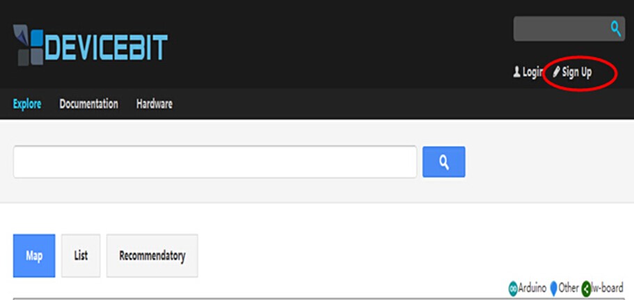
Log in on the website (http://www.devicebit.com/) as shown in Fig 5.1. Click Sign Up on the top right corner of the page.
The following page will appear, as shown in Fig 5.2. Enter your username, password, and Email. Then log into your mailbox to activate your account.
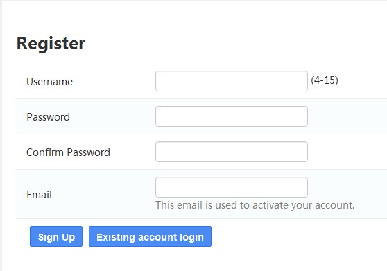
Fig 5.2
Add a New Device
Log in to your account,then go to User Center, and go to My Devices -> Devices -> Add A device, as shown in Fig 5.3.
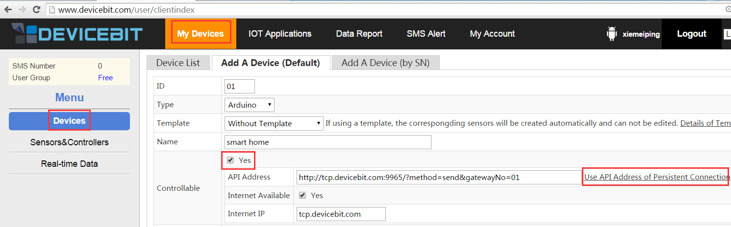
Fig 5.3
Fill in the related information and then click Save.
The related parameters are explained as follows:
1) ID: The ID of the device, allocated by system automatically. It is unique for each device.
2) Type: The type of the device. Click the inverted triangle and the following options will appear.
丨 Arduino: Arduino Board.
丨 Lw-board: The board developed by DeviceBit.
丨 Other: Other boards.
3) Name: The name of the device. For example, Smart Home
4) Description: Description of the device.
5) Public: If your devices are public, other users can also view them and their measurement.
6) Location: The location of your device. Click the location point on the Map.
Add a New Sensor or Controller
The next step is to add a new sensor or controller connected to your device.
- Add a new sensor
As shown in Fig 5.4, go to My Devices -> Sensors&Controllers -> Sensors,and then click Add to create a new sensor.
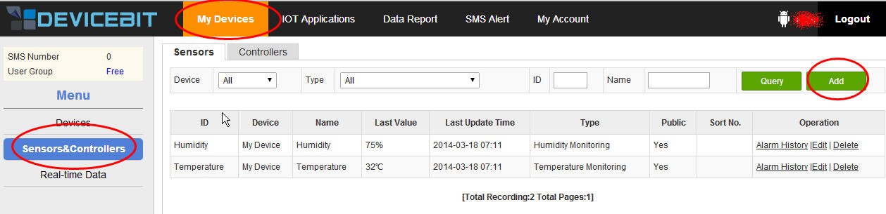
Fig 5.4
Now, the following page will appear, as shown in Fig 5.5:
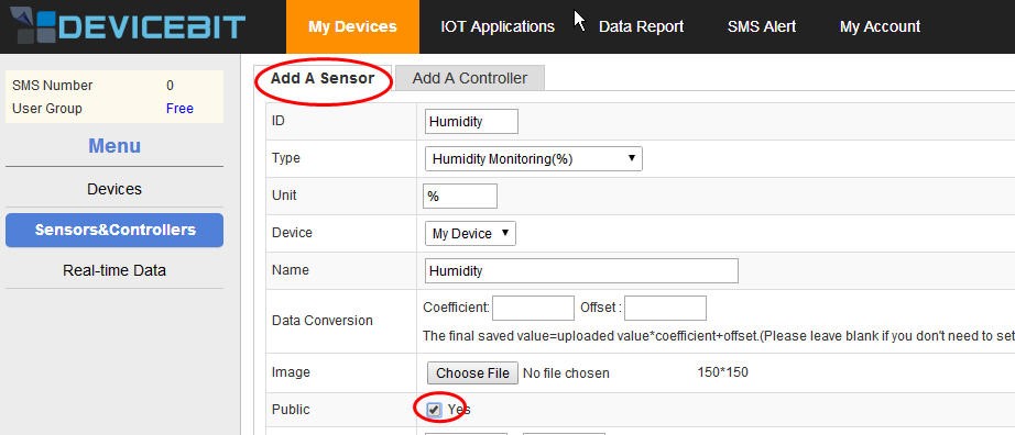
Fig 5.5
Fill in the related information and then click Save.
The related parameters are explained as follows:
1) ID: The ID of the new sensor. It is unique for each sensor.
2) Type: The type of the new sensor.
3) Unit: The unit of the measurement.
4) Device: Select the device which the sensor is to be connected to.
5) Name: The name of the new sensor.
6) Data Conversion: To calibrate your sensor’s measurement. You can enter Coefficient and Offset if applicable.
7) Picture: Upload the picture of your sensor.
8) Public: If your sensors are public, other users can also view them and their measurement.
9) Normal range: The normal range of the sensor’s measurement. You can set it according to your actual need.
10) Overrange alarm: Turn it on and you will receive the alert by SMS or email when the sensor’s measurement is out of the range.
11) Data post period: The system indicates that the sensor is OFFLINE if it does not get the data posted by the sensor within every data post period set here.
12) Remark: Remark of the sensor.
- Add a new controller
As shown in Fig 5.6, go to My Devices -> Sensors&Controllers -> Controllers,and then click Add to add a new controller.
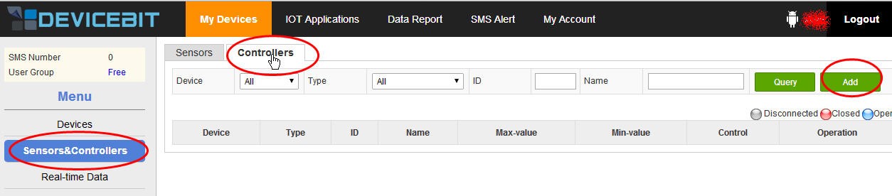
Fig 5.6
Now, the following page will appear, as shown in Fig 5.7:
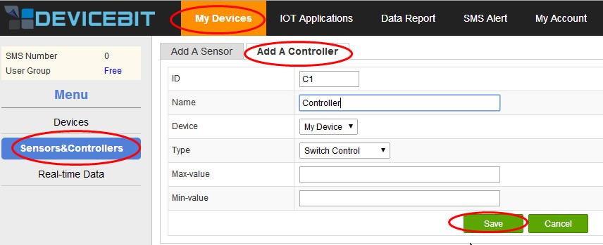
Fig 5.7
Fill in the related information and then click Save.
The related parameters are explained as follows:
1) ID: The ID of the new controller. It is unique for each controller.
2) Name: The name of the new controller.
3) Device: To select the device which the controller is connected to.
4) Type: The type of the new controller, which can be Switch Control or Numerical Control. For switch type, 0 or 1 is used to control the switch, while for numerical type, the controller status is adjusted by different numerical values.
5) Max-value: The max-value for numerical type.
6) Min-value: The min-value for numerical type.
How to Operate Control Board
Control boards are divided into acquisition board and control board. The acquisition board is mainly composed of SunFounder Mega 2560 and W5100. It is used to collect sensor data, upload the data to the DeviceBit platform, receive control commands from DeviceBit, and finally send these commands to the control board via the wireless RF module. The control board will operate accordingly after receiving these commands. That is the working process of the control board terminal. More specific steps are subsequently described.
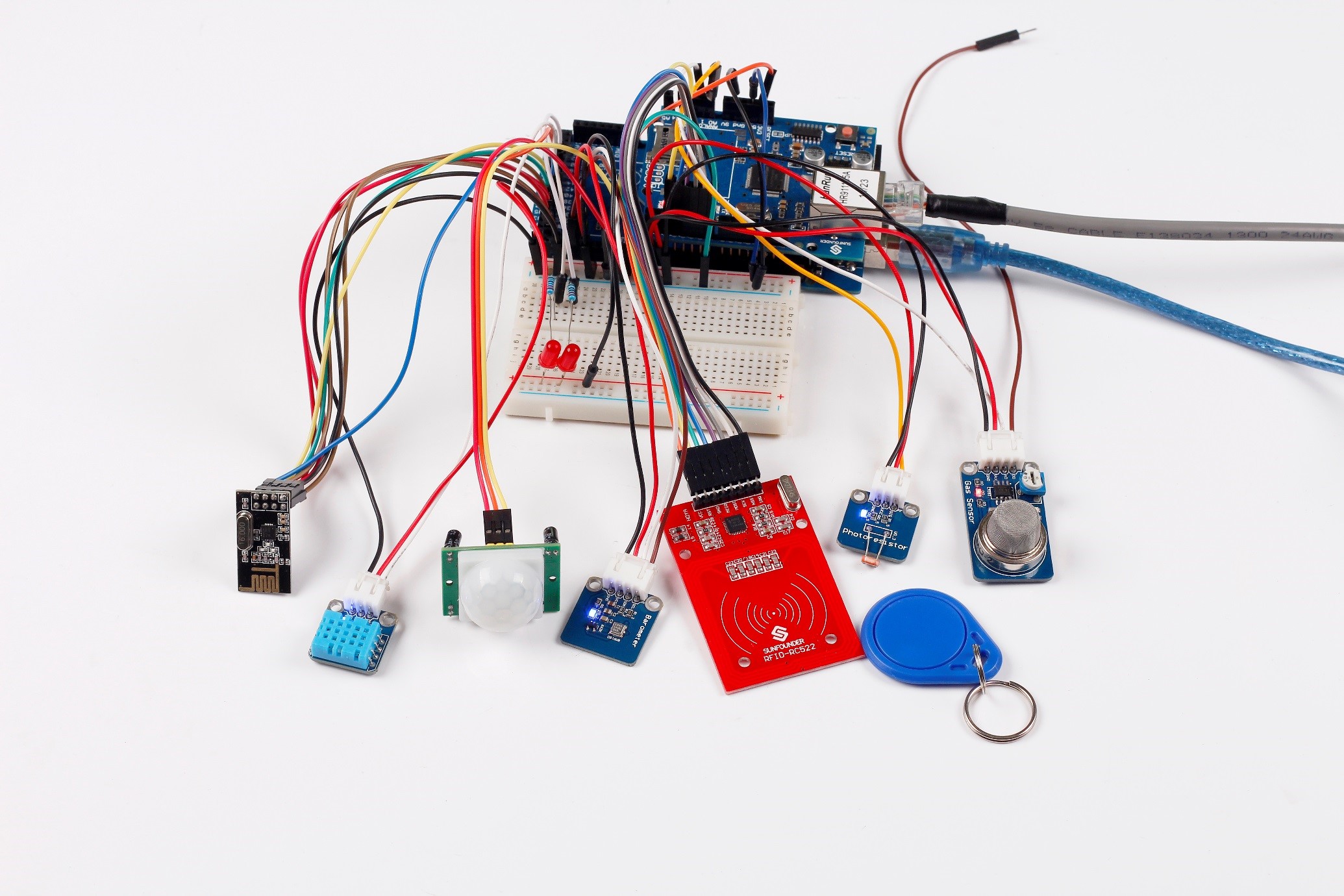
Acquisition board
Components:
-1 * SunFounder Mega 2560
-1 * W5100
-1 * DHT11
-1 * Photoresistor module
-1* Gas sensor MQ-2
-1 * RFID-RC522
-1 * PIR
-1 * Gas pressure sensor BMP180
-1 * NRF24L01
-2 * LED
-2 * 220Ohm Resistor
-1 * USB Cable
-1 * Breadboard
-Several jumper wires
-1 * USB Cable for SunFounder Mega 2560
-2 * 4-Pin Anti-reverse Cable
-2 * 3-Pin Anti-reverse Cable
Experimental Procedures
Step1: Build the circuit
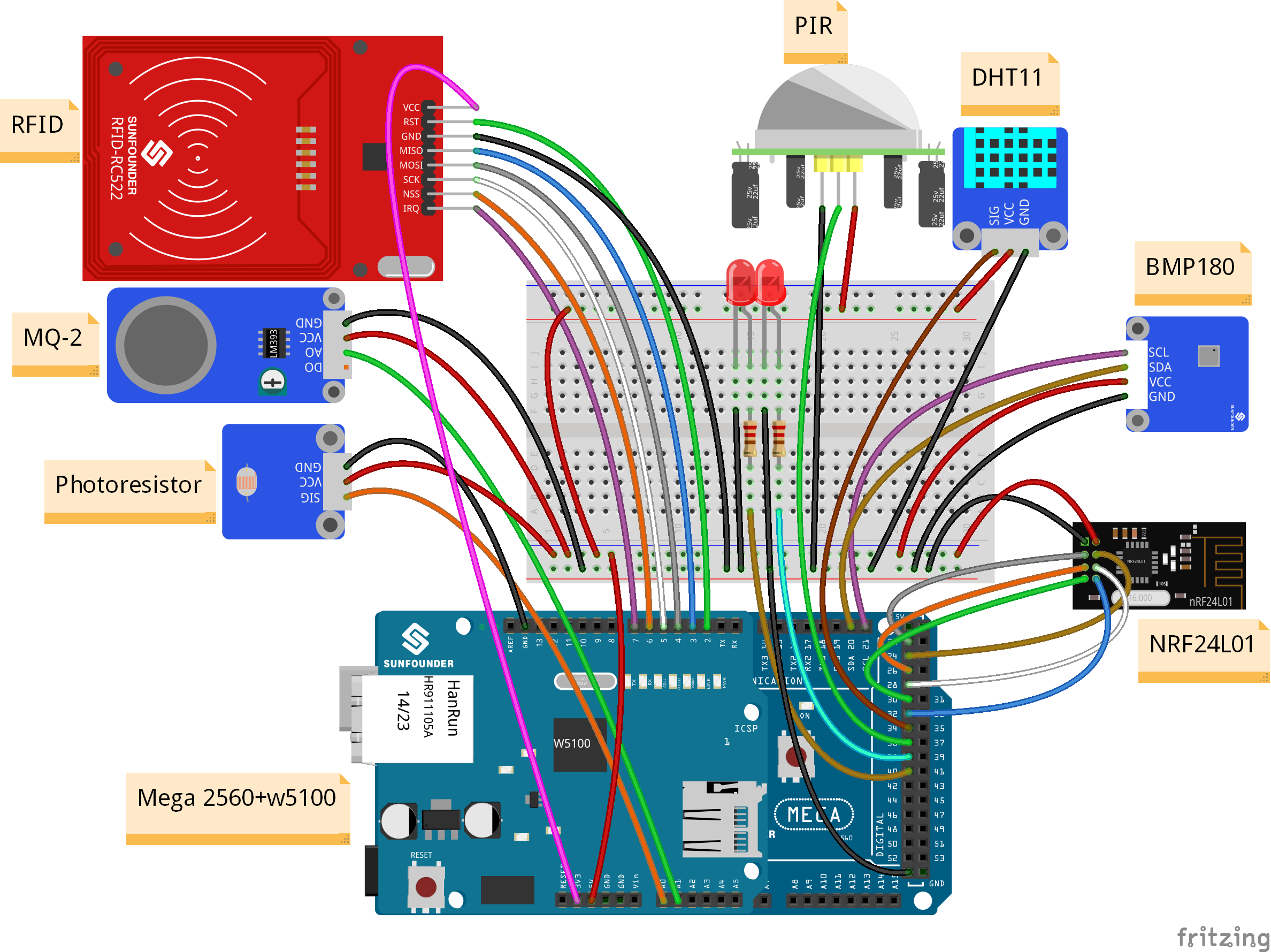
1) Connect W5100 and SunFounder Mega 2560. Align the related pins.
2) Connect DHT11 and SunFounder Mega 2560
| DHT11 | SunFounder Mega 2560 |
| SIG | 34 |
| VCC | 5v |
| GND | GND |
3) Connect Photoresistor Module and SunFounder Mega 2560
| Photoresistor Module | SunFounder Mega 2560 |
| SIG | A0 |
| VCC | 5v |
| GND | GND |
4) Connect MQ-2 Module and SunFounder Mega 2560
| MQ-2 Module | SunFounder Mega 2560 |
| D0 | N/C |
| A0 | A1 |
| GND | GND |
| VCC | 5V |
5) Connect PIR Module and SunFounder Mega 2560
| PIR Module | SunFounder Mega 2560 |
| OUT | 36 |
| VCC | 5v |
| GND | GND |
6) Connect RFID Module and SunFounder Mega 2560
| RFID | SunFounder Mega 2560 |
| VCC | 3.3V |
| RST | 2 |
| GND | GND |
| MISO | 3 |
| MOSI | 4 |
| SCK | 5 |
| NSS | 6 |
| IRQ | 7 |
7) Connect NRF24L01 Module and SunFounder Mega 2560
| NRF24L01 | SunFounder Mega 2560 |
| CE | 22 |
| CSN | 24 |
| SCK | 26 |
| MOSI | 28 |
| MISO | 30 |
| IRQ | 32 |
| GND | GND |
| VCC | 3.3V |
8) Connect BMP180 Module and SunFounder Mega 2560
| BMP180 Module | SunFounder Mega 2560 |
| SCL | SCL(21) |
| SDA | SDA(20) |
| GND | GND |
| VCC | 5V |
9) Connect a 220Ohm resistor and an LED in series to pin 38 on SunFounder Mega 2560. Connect another 220Ohm resistor and another LED in series to pin 40 on SunFounder Mega 2560. These two LEDs are used to indicate the status of the RFID and PIR.
The wiring of the acquisition board is as follows:
Step 2: Program
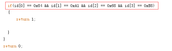
1) After you get the acquisition board wired, divide the ID of the RFID key tag (e.g. 84A168B8 in this experiment) obtained in Experiment 6 into four groups and fill them in the Acquisition_board.ino file, as shown in the following code (see Line 742 in Arduino IDE).
Note: If you change anther RFID key tag, you need to obtain the ID of RFID key tag again and upload the getID.ino file to SunFounder Mega 2560.
2) Before connecting W5100 to the Internet, you need to know your password on Devicebit. Go to User Center, click My Account ->Account Settings, and then you can see your Userkey, as shown in Fig 5.8.
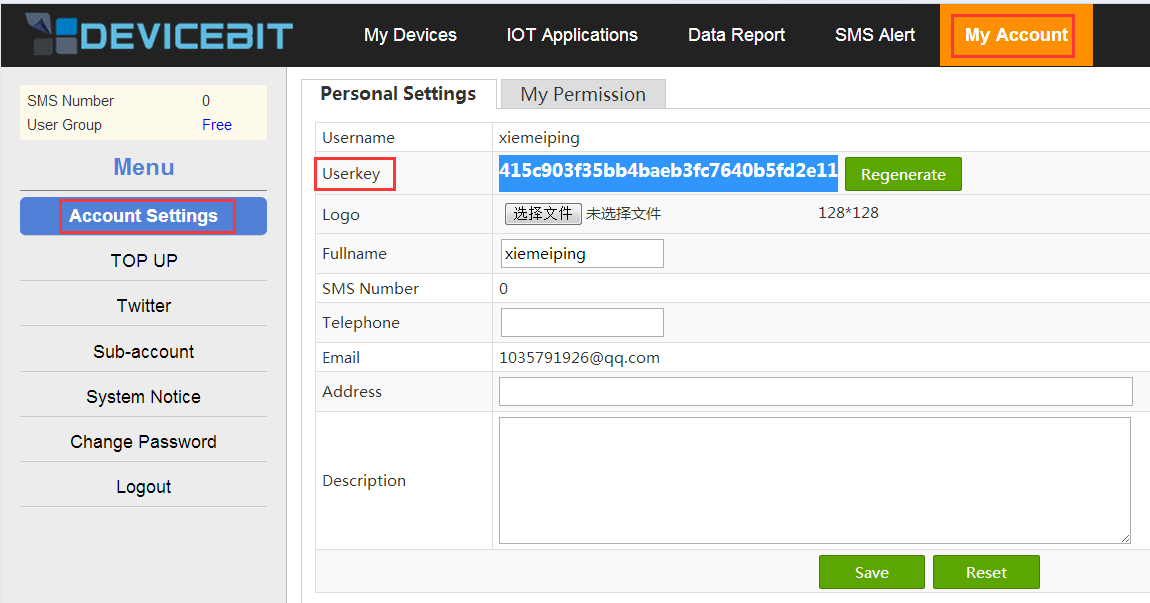
Fig 5.8
Copy and paste the value of Userkey in the following code. The gateway number is your device ID on the Devicebit platform. You can click My Devices ->Devices in User Center. Select your device ID (here the device is Smart Home, and ID: 01), as shown in Fig 5.9
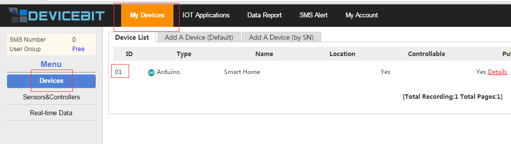
Fig 5.9
3) Download the arduino IDE from www.arduino.cc. Remember to select the version 1.0.5, not the latest version 1.6.5 by now. (We have provided Arduino 1.0.5.zip, so you can use it by unzipping it)
4) Plug network cable to W5100
Step 3: Compile (Acquisition_board.ino)
Program description
Since you need to detect the status of RFID and PIR in real time, upload the data to the DeviceBit platform, and many delays should be used. If you place the code that is used to detect the status of RFID and PIR in the main() loop, it will severely affect the real-time performance. As a result, you should use timer 1 of the master chip to regularly detect the status of RFID and PIR to ensure the real-time effect. The timer 1 is actually easy to use – just set several registers. The registers used here are TCCR1A (T/C1 control register A), TCCR1B (T/C1 control register B), TCNT1 (16-bit counting register), TIMSK (interrupt mask register) and SREG (interrupt register).
TCCR1A: Since you only use the timing overflow interrupt of timer 1 here, set it to 0 to mask the output function of PWM.
TCCR1B: Here you only need to set the CS12, CS11, and CS10 bit of TCCR1B to 1, 0, and 1. That is, select the 1024 frequency division.
TCNT1: This register is used to set the timing initial value of the timer. Set it to 65536 – F_CPU/F_DIV * TIME, F_CPU (the main frequency of the master board) to 16000000 (16MHz), F_DIV (frequency dividing ratio) to 1024. For TIME (timing length), define it as 0.1. That means it will go to the interrupt service program of timer 1 to perform corresponding tasks every 0.1 second. The task here is to query the status of PIR and RFID.
TIMSK: This register can be used to turn timers on and off. The timer 1 is opened once TOIE1 is set to 1.
SREG: Once the flag bit I is set to 1, we can open the master switch of the interrupt. The TOIE1 setting of timer 1 can take effect only if the master switch of the interrupt is opened.
The interrupt service routine for timer 1 corresponds to the ISR (TIMER1 OVR vector) function. Once the interrupt service routine begins, the 16-bit counting register will be reset. So you need to reload the initial value, that is, to call “TCNT1 = 65536 – F_CPU/F_DIV *TIME;” statement again in the interrupt service routine.
Step 4: Burn the program into the SunFounder Mega 2560 board
Control Board
Components:
-1 * SunFounder Nano
-1 * NRF24L01
-1 * 4-channel Relay Module
-1 * USB Cable for Nano
Experimental Procedures
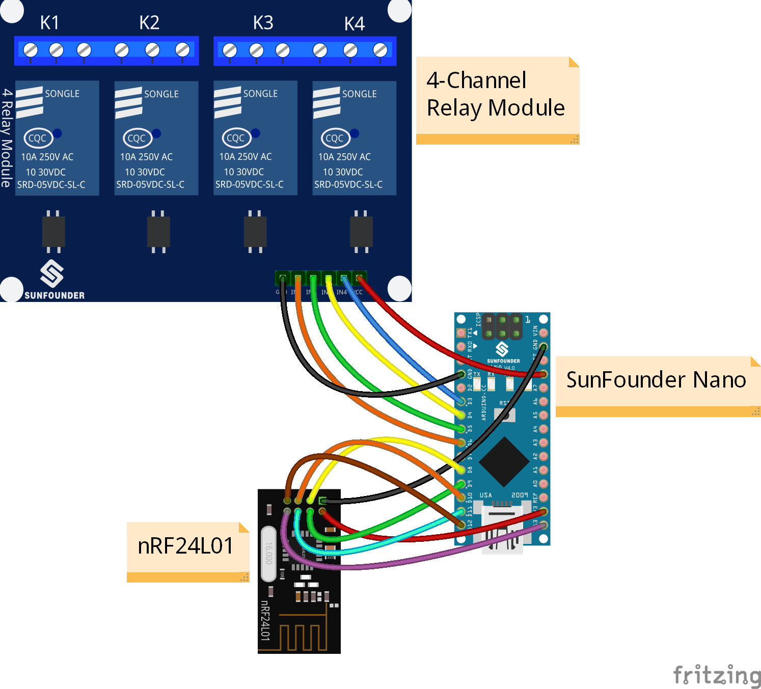
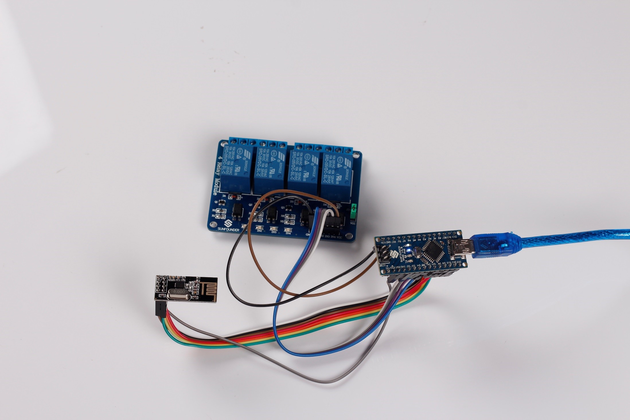
Step1: Build the circuit
1) Connect NRF24L01 and SunFounder Nano:
| NRF24L01 | SunFounder Nano |
| CE | 8 |
| CSN | 9 |
| SCK | 10 |
| MOSI | 11 |
| MISO | 12 |
| IRQ | 13 |
| GND | GND |
| VCC | 3.3V |
2) Connect the 4-Channel Relay Module and SunFounder Nano:
| 4-Channel Relay Module | SunFounder Nano |
| IN1 | 6 |
| IN2 | 5 |
| IN3 | 4 |
| IN4 | 3 |
| VCC | 5V |
| GND | GND |
Step2: Program (see the Control_Board.ino file)
Step3: Compile
Step4: Upload the sketch into the SunFounder Nano board
After all the above steps, visit http://www.devicebit.com/home/publicsensors to enter the DeviceBit platform. Click User Center on the top right corner of the page (If you have already logged in). You will see the page as shown in Fig 5.10:
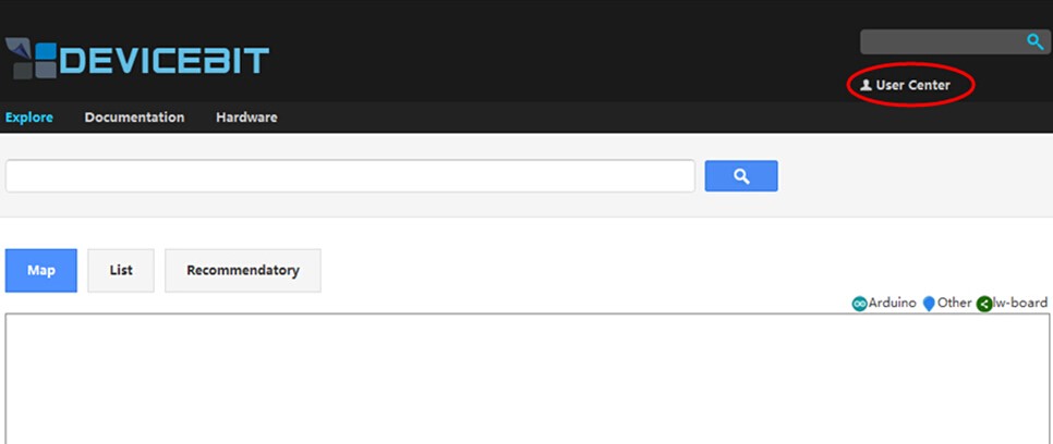
Fig 5.10
If you have not logged in, click Login, as shown in Fig 5.11:
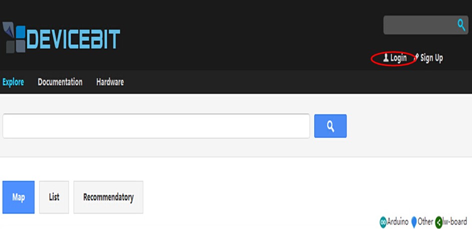
Fig 5.11
Fill in your Username, Password and Verification Code, as shown in Fig 5.12:
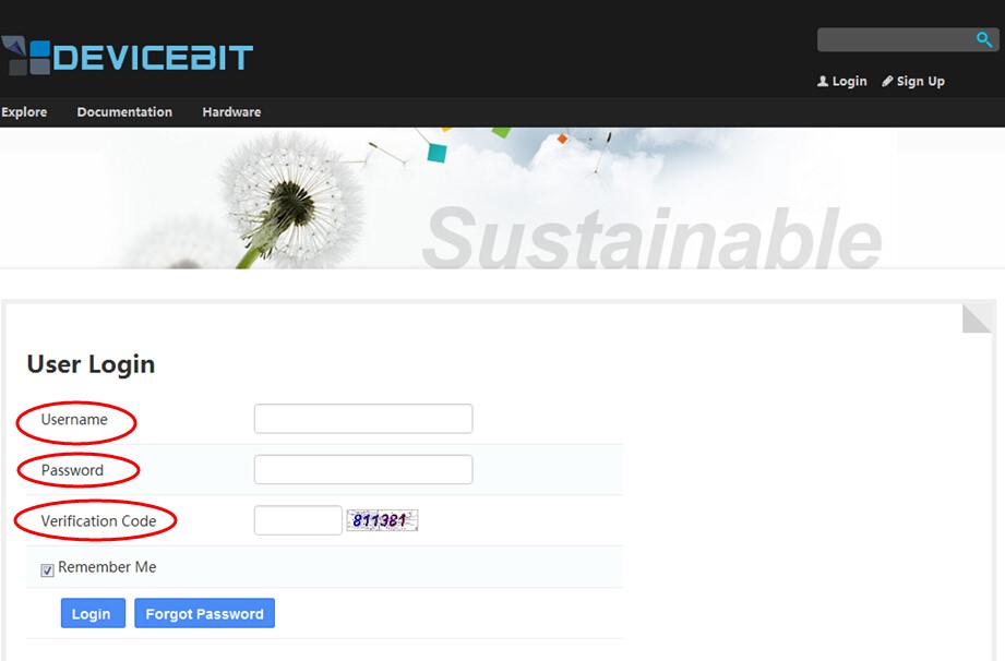
Fig 5.12
After entering into User Center, you will see the page as shown in Fig 5.13:
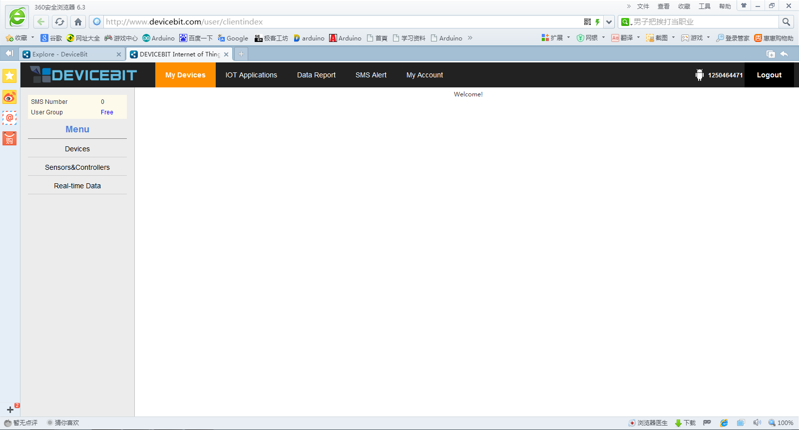
Fig 5.13
Click Devices, and the following page will appear (Fig 5.14)
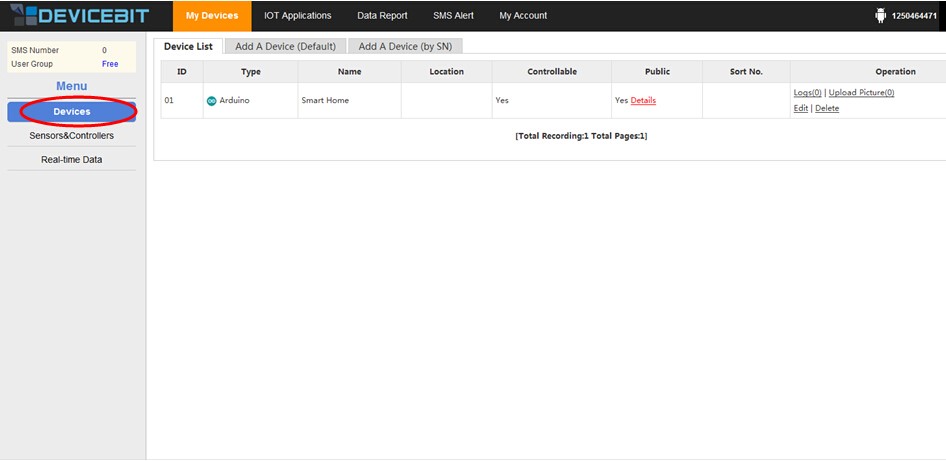
Fig 5.14
Click the red link “Details” to see your device details, as shown in Fig 5.15:
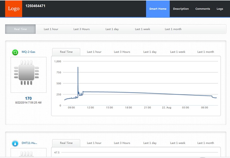
Fig 5.15
Return to the page as shown in Fig 5.13, and click Sensors&Controllers on the left side to see your sensors and controllers, as shown in Fig 5.16:
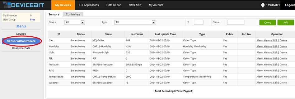
Fig 5.16
Click Controllers to see your controllers, as shown in Fig 5.17:
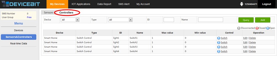
Fig 5.17
If everything goes well, the status icon of Switch should be displayed blue, which indicates that your master control board has been connected to the DeviceBit platform. Click Switch. If the icon changes from blue to red, check the status of your relay on the receiving board; if it works normally, the corresponding relay should pull in, and the corresponding LED light will light up. Click Switch again. If the icon changes back from red to blue, check the relay status; if it works normally, the LED light should go out, and the corresponding relay should be disconnected.
Back to the page as shown in Fig 5.13, and click Real-time Data on the left side to see the real-time data of your sensor, as shown in Fig 5.18:
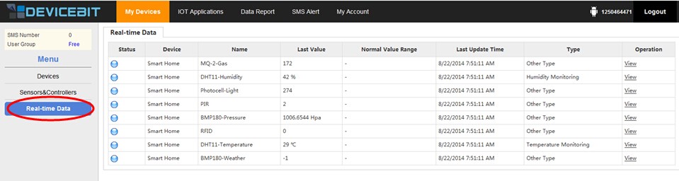
Fig 5.18
If your master control board is connected to the Devicebit platform and works normally, the status indicator of the corresponding sensor on the left side should be displayed blue; otherwise, grey. Click View on the right side to see the corresponding curve of the sensor, as shown in Fig 5.19:
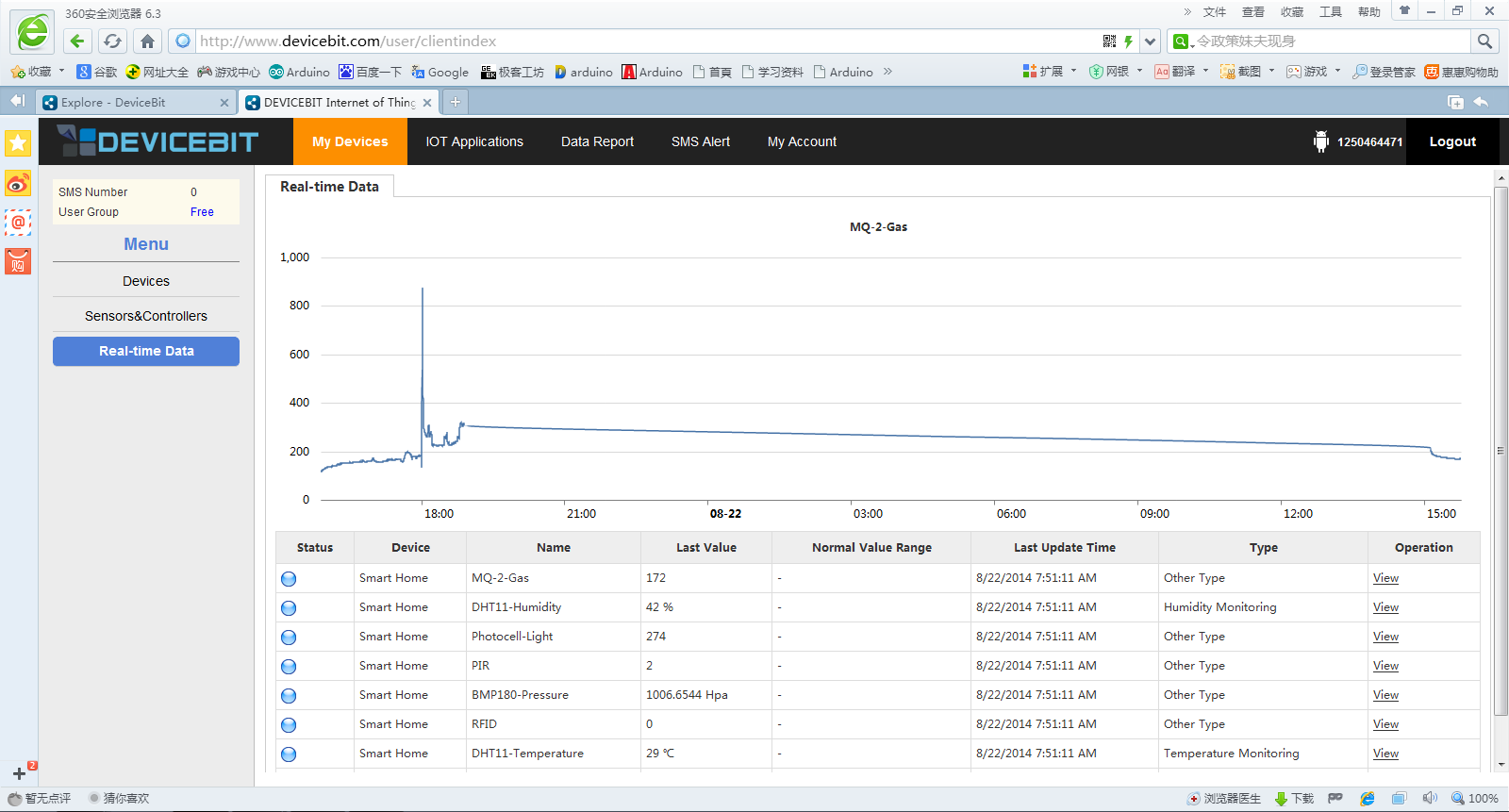
Fig 5.19
How to Operate Web App on Mobile Phone
1) Visit m.devicebit.com on your mobile phone to enter into the DeviceBit platform, as shown in Fig 5.20:
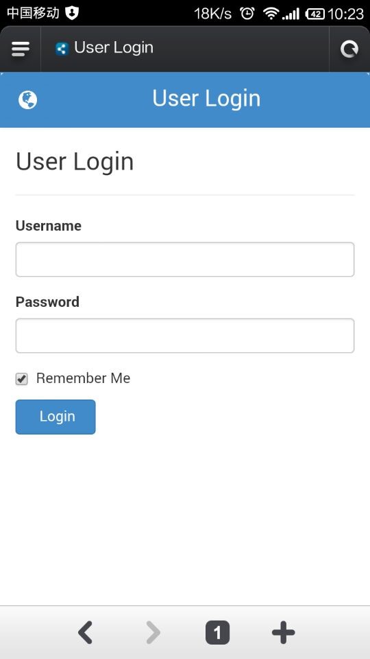
Fig 5.20
2) After login, it is as shown in Fig 5.21
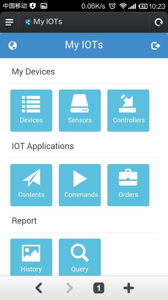
Fig 5.21
3) Click Devices icon, as shown in Fig 5.22
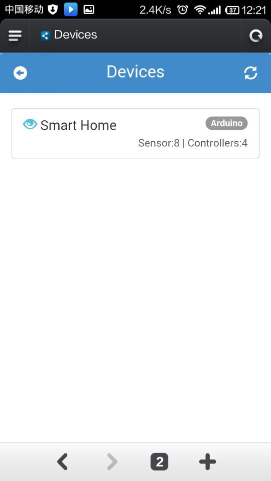
Fig 5.22
The figure above shows the number of sensors and controllers. Click the back icon on the top left corner to return to the main page as shown in Fig 5.21, and then click the Sensors icon, as shown in Fig 5.23
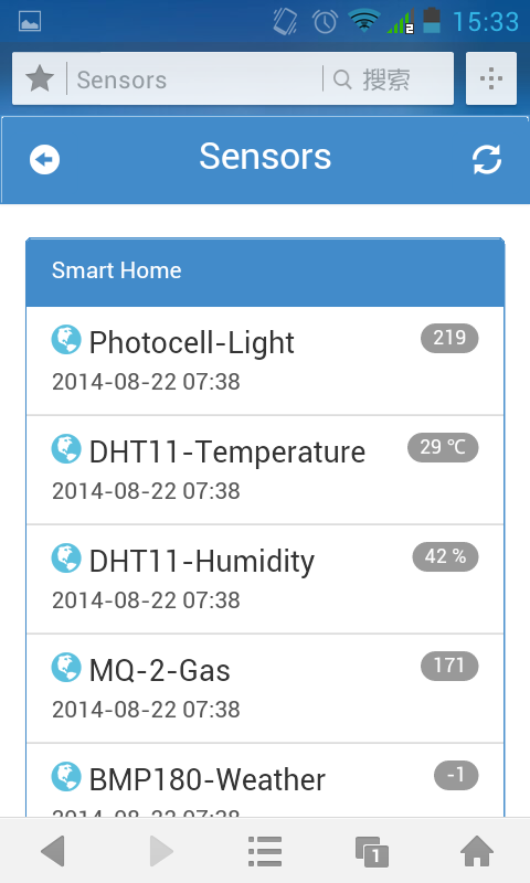
Fig 5.23
Click the back icon on the top left corner to return to the upper level page in Fig 5.22, and then click Controllers.
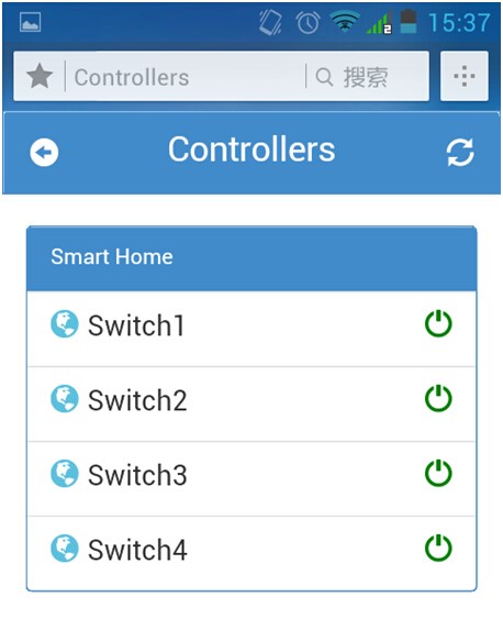
Fig 5.24
If the connection between your master control board and the DeviceBit platform works normally, the switch icons will be green; otherwise; grey. Click any switch icon, and you will see the icon changed from green to red. Check your receiving terminal. If everything goes well, the corresponding relay will be energized and the corresponding LED will light up.
Summary
This user manual details how to DIY a simple Smart Home system with SunFounder Mega 2560 and W5100. Through hands-on practice, you should have mastered a more visual recognition on the Internet of Things. Of course this is only the first step you set your foot in the field of the Internet of Things. After the learning, you can make further exploration and create more interesting projects. For more information about the DeviceBit platform, go to http://www.devicebit.com/dev/docList?cid=0103&sk=72.