Overview:
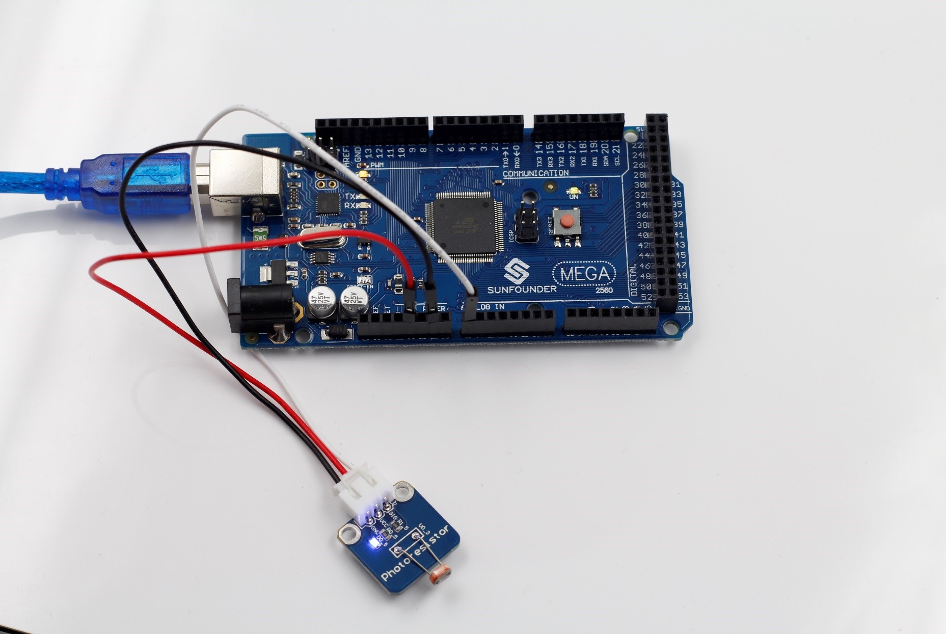
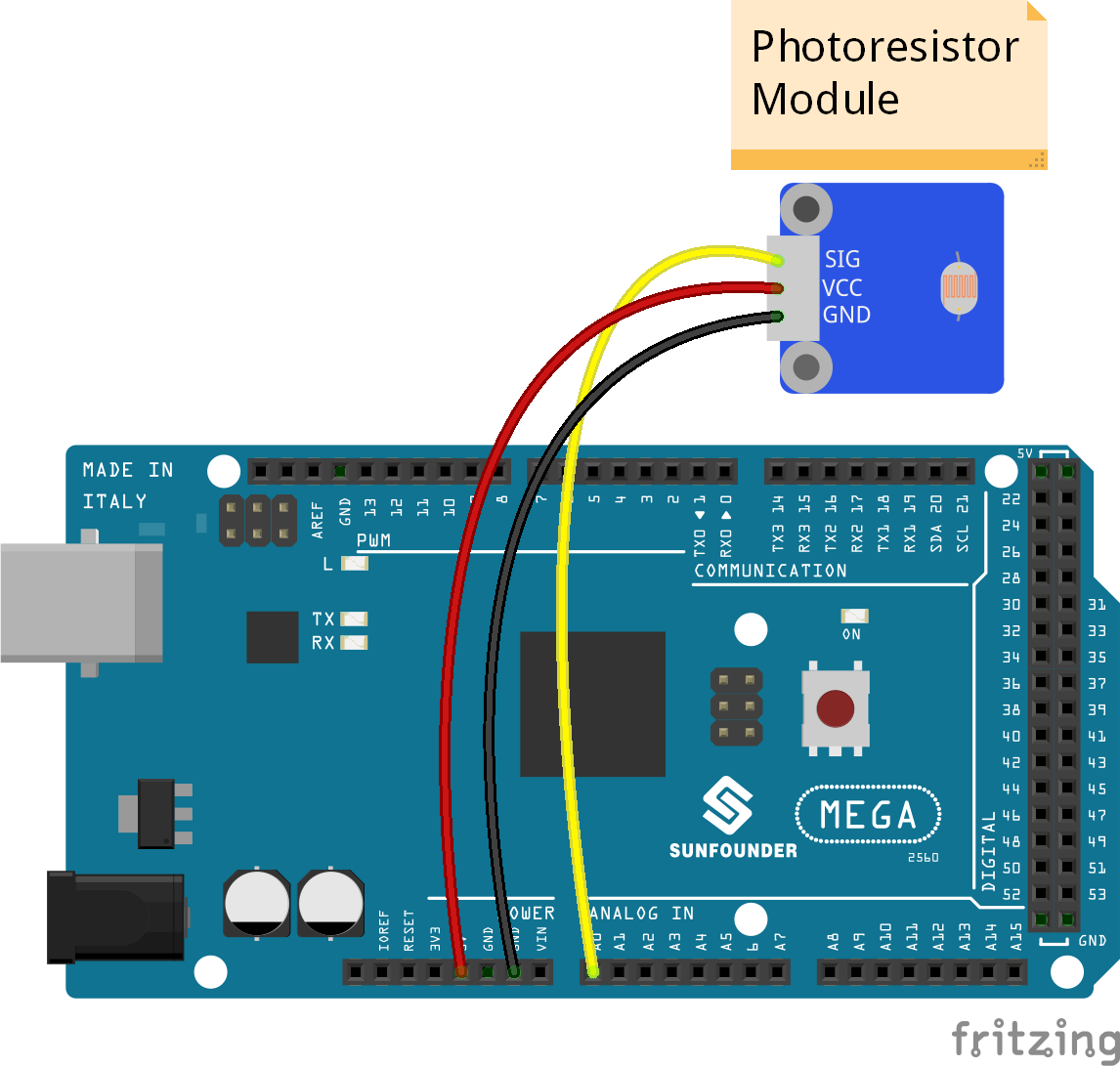
In this experiment, connect the photoresistor to pin A0 of SunFounder Mega 2560. When the light intensity changes, the resistance of the photoresistor will change and the output voltage of A0 will change accordingly. The resistance of the photoresistor is regulated and converted by the A/D converter inside the SunFounder Mega 2560 into digital values which you can see on Serial Monitor. The stronger the light intensity is, the smaller the value is; the weaker, the larger.
Components:
– 1 * SunFounder Mega 2560
– 1 * Photoresistor Module
– 1 * USB Cable
– 1 * 3-Pin anti-reverse cable
Experimental Procedures
Step1: Build the circuit
Step2: Program
Step3: Compile
Step4: Burn the program into the SunFounder Mega 2560 board
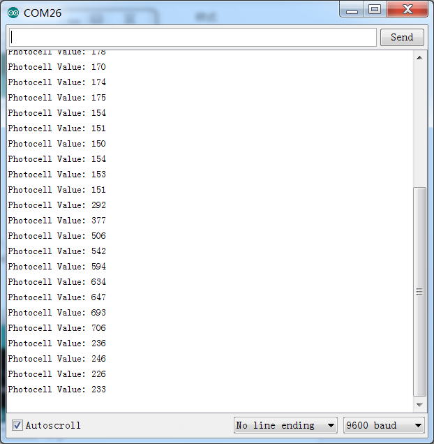
Open the serial monitor and you can see the resistance of the photoresistor changing. Cover the photoresistor with your palm and the value displayed on Serial Monitor will increase. Move it away and the value displayed will decrease and finally tend to be stable.