Overview:
In this experiment, you will learn how to use the RFID module and RFID1 library, and simulate SPI with software to communicate between the SunFounder Mega 2560 board and the RFID module. Before starting, you need to know the ID of the RFID key tag and write the ID to the rfidTest file.
After you have finished the following steps, if you place the RFID key tag in the induction zone of the RFID module, the characters ”Collect!” will be displayed on Serial Monitor.
Components:
-1 * SunFounder Mega 2560
-1 * RFID Module
-1 * RFID key tag
-1 * USB Cable
– Several jumper wires
-1 * Breadboard
-1* Capacitor Ceramic 100nF
Experimental Procedures
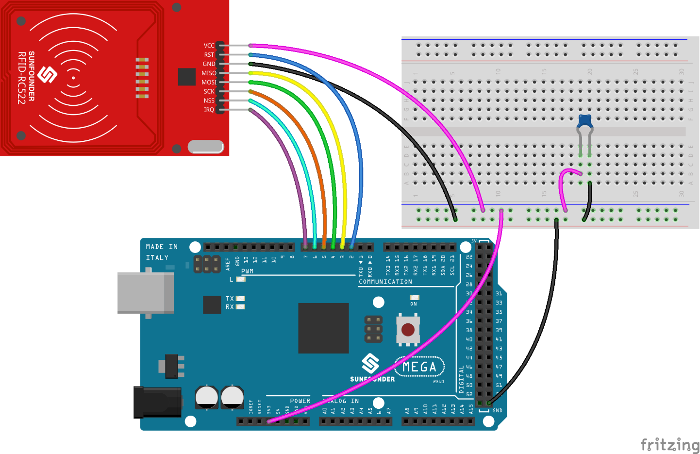
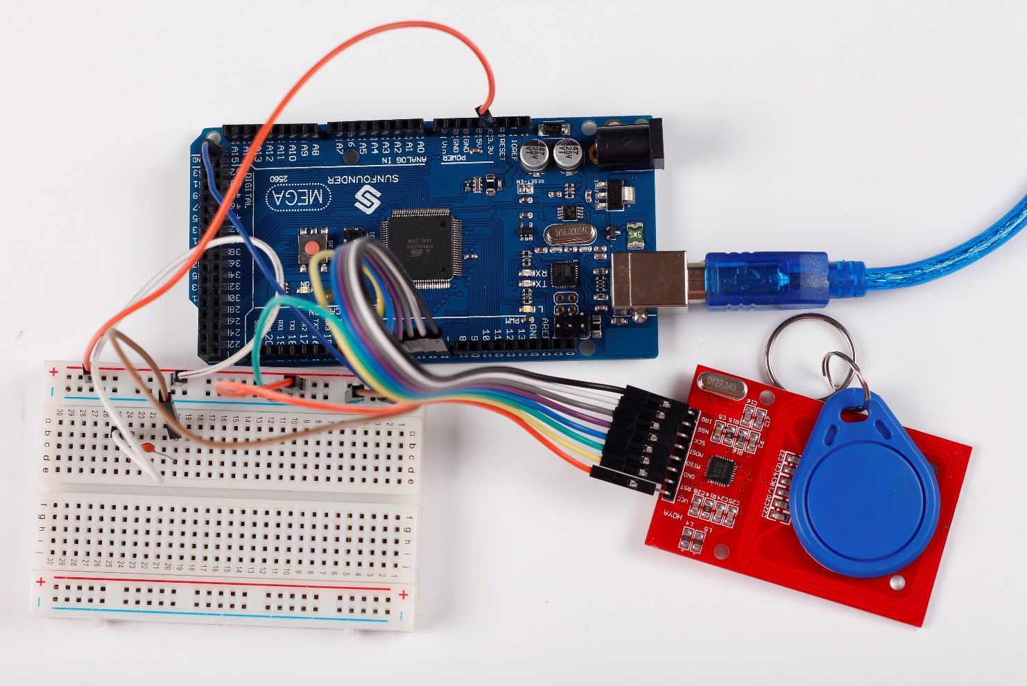
Step1: Build the circuit
The wiring between RFID and SunFounder Mega 2560 is as follows:
| RFID | SunFounder Mega 2560 |
| VCC | 3.3V |
| RST | 2 |
| GND | GND |
| MISO | 3 |
| MOSI | 4 |
| SCK | 5 |
| NSS | 6 |
| IRQ | 7 |
Note: To realize more stable output, you need to connect a 0.1uF capacitor between 3.3V and GND for filtering.
Step 2: Open the getId file with Arduino IDE (Please refer to the example code in LEARN -> Get Tutorial on our website). Compile the code
Step 3: Upload the sketch to the SunFounder Mega 2560 board
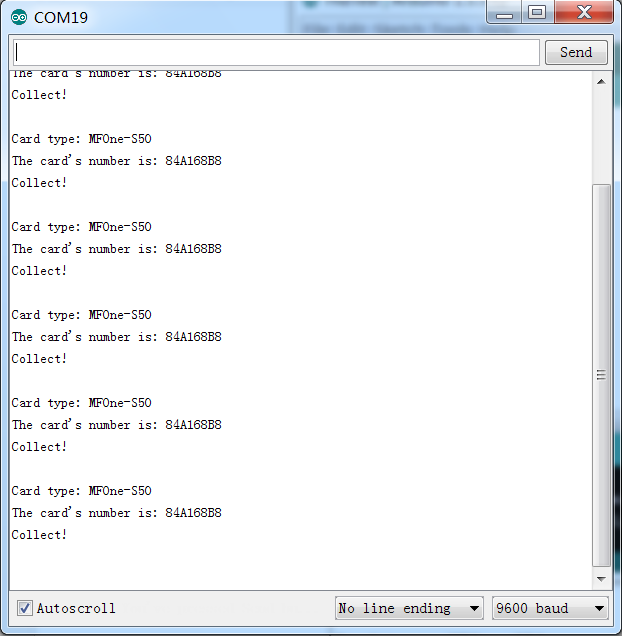
Then place the RFID key tag in the induction zone of the RFID module. You will see the following values printed on Serial Monitor:
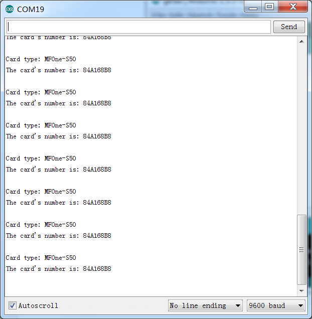
Step 4: Now, you may know the ID of your RFID key tag (e.g. the RFID key tag in our experiment is 84A168B8, as shown in the figure above).
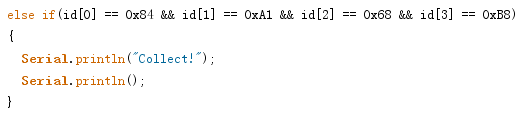
Open the rfidTest file and replace the ID in the sketch with your own (divide the ID into four numbers equally, just as shown in the example below):
Step 5: Burn the sketch into the SunFounder Mega 2560 board
After burning rfidTest, you will see the following values printed on Serial Monitor: