Introduction
In this project, we sequentially illuminate the lights on the LED Bar Graph.
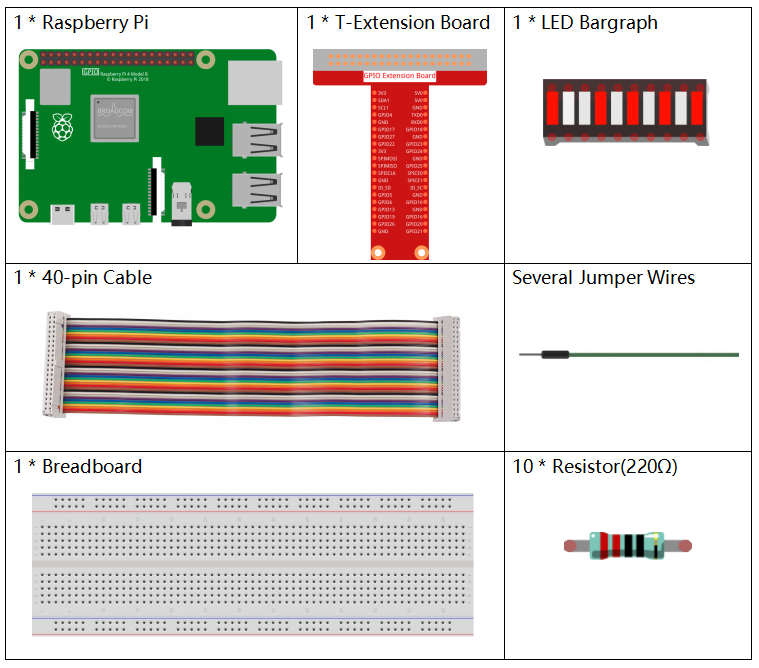
Components
Principle
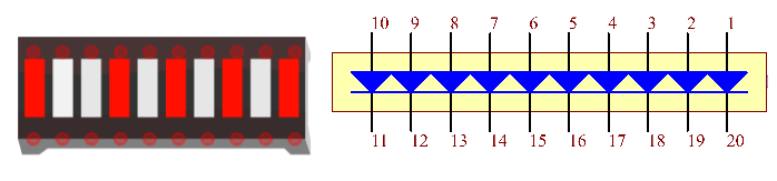
LED Bar Graph
LED Bar Graph is an LED array, which is used to connect with electronic circuit or microcontroller. It’s easy to connect LED bar graph with the circuit like as connecting 10 individual LEDs with 10 output pins. Generally we can use the LED bar graph as a Battery level Indicator, Audio equipments, and Industrial Control panels. There are many other applications of LED bar graphs.
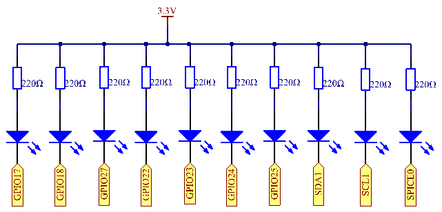
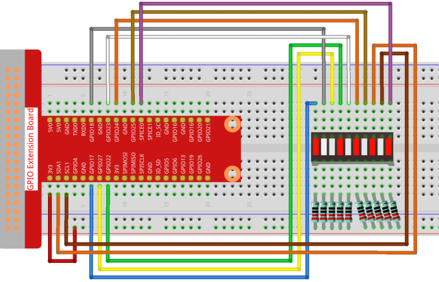
Schematic Diagram
| T-Board Name | physical | wiringPi | BCM |
| GPIO17 | Pin 11 | 0 | 17 |
| GPIO18 | Pin 12 | 1 | 18 |
| GPIO27 | Pin 13 | 2 | 27 |
| GPIO22 | Pin 15 | 3 | 22 |
| GPIO23 | Pin 16 | 4 | 23 |
| GPIO24 | Pin 18 | 5 | 24 |
| GPIO25 | Pin 22 | 6 | 25 |
| SDA1 | Pin 3 | 8 | 2 |
| SCL1 | Pin 5 | 9 | 3 |
| SPICE0 | Pin 24 | 10 | 8 |
Experimental Procedures
Step 1: Build the circuit.
- For C Language Users
Step 2: Go to the folder of the code.
cd ~/davinci-kit-for-raspberry-pi/c/1.1.3/Step 3: Compile the code.
gcc 1.1.3_LedBarGraph.c -lwiringPiStep 4: Run the executable file.
sudo ./a.outAfter the code runs, you will see the LEDs on the LED bar turn on and off regularly.
Code
#include <wiringPi.h>
#include <stdio.h>

int pins[10] = {0,1,2,3,4,5,6,8,9,10};
void oddLedBarGraph(void){
    for(int i=0;i<5;i++){
        int j=i*2;
        digitalWrite(pins[j],HIGH);
        delay(300);
        digitalWrite(pins[j],LOW);
    }
}
void evenLedBarGraph(void){
    for(int i=0;i<5;i++){
        int j=i*2+1;
        digitalWrite(pins[j],HIGH);
        delay(300);
        digitalWrite(pins[j],LOW);
    }
}
void allLedBarGraph(void){
    for(int i=0;i<10;i++){
        digitalWrite(pins[i],HIGH);
        delay(300);
        digitalWrite(pins[i],LOW);
    }
}
int main(void)
{
    if(wiringPiSetup() == -1){ //when initialize wiring failed,print message to screen
        printf("setup wiringPi failed !");
        return 1;
    }
    for(int i=0;i<10;i++){       //make led pins' mode is output
        pinMode(pins[i], OUTPUT);
        digitalWrite(pins[i],LOW);
    }
    while(1){
        oddLedBarGraph();
        delay(300);
        evenLedBarGraph();
        delay(300);
        allLedBarGraph();
        delay(300);
    }
    return 0;
}
Code Explanation
int pins[10] = {0,1,2,3,4,5,6,8,9,10};Create an array and assign it to the pin number corresponding to the LED Bar Graph (0,1,2,3,4,5,6,8,9,10) and the array will be used to control the LED.
void oddLedBarGraph(void){
    for(int i=0;i<5;i++){
        int j=i*2;
        digitalWrite(pins[j],HIGH);
        delay(300);
        digitalWrite(pins[j],LOW);
    }
}
Let the LED on the odd digit of the LED Bar Graph light on in turn.
void evenLedBarGraph(void){
    for(int i=0;i<5;i++){
        int j=i*2+1;
        digitalWrite(pins[j],HIGH);
        delay(300);
        digitalWrite(pins[j],LOW);
    }
}
Make the LED on the even digit of the LED Bar Graph light on in turn.
void allLedBarGraph(void){
    for(int i=0;i<10;i++){
        digitalWrite(pins[i],HIGH);
        delay(300);
        digitalWrite(pins[i],LOW);
    }
}
Let the LED on the LED Bar Graph light on one by one.
- For Python Language Users
Step 2: Go to the folder of the code.
cd /home/pi/davinci-kit-for-raspberry-pi/python/Step 3: Run the executable file.
sudo python3 1.1.3_LedBarGraph.pyAfter the code runs, you will see the LEDs on the LED bar turn on and off regularly.
Code
import RPi.GPIO as GPIO
import time

ledPins = [11, 12, 13, 15, 16, 18, 22, 3, 5, 24]

def oddLedBarGraph():
    for i in range(5):
        j = i*2
        GPIO.output(ledPins[j],GPIO.HIGH)
        time.sleep(0.3)
        GPIO.output(ledPins[j],GPIO.LOW)

def evenLedBarGraph():
    for i in range(5):
        j = i*2+1
        GPIO.output(ledPins[j],GPIO.HIGH)
        time.sleep(0.3)
        GPIO.output(ledPins[j],GPIO.LOW)

def allLedBarGraph():
    for i in ledPins:
        GPIO.output(i,GPIO.HIGH)
        time.sleep(0.3)
        GPIO.output(i,GPIO.LOW)

def setup():
    GPIO.setwarnings(False)
    GPIO.setmode(GPIO.BOARD)        # Numbers GPIOs by physical location
    for i in ledPins:
        GPIO.setup(i, GPIO.OUT)   # Set all ledPins' mode is output
        GPIO.output(i, GPIO.LOW) # Set all ledPins to high(+3.3V) to off led

def loop():
    while True:
        oddLedBarGraph()
        time.sleep(0.3)
        evenLedBarGraph()
        time.sleep(0.3)
        allLedBarGraph()
        time.sleep(0.3)

def destroy():
    for pin in ledPins:
        GPIO.output(pin, GPIO.LOW)    # turn off all leds
    GPIO.cleanup()                     # Release resource

if __name__ == '__main__':     # Program start from here
    setup()
    try:
        loop()
    except KeyboardInterrupt:  # When 'Ctrl+C' is pressed, the program destroy() will be  executed.
        destroy()
Code Explanation
ledPins = [11, 12, 13, 15, 16, 18, 22, 3, 5, 24]Create an array and assign it to the pin number corresponding to the LED Bar Graph (11, 12, 13, 15, 16, 18, 22, 3, 5, 24) and the array will be used to control the LED.
def oddLedBarGraph():
    for i in range(5):
        j = i*2
        GPIO.output(ledPins[j],GPIO.HIGH)
        time.sleep(0.3)
        GPIO.output(ledPins[j],GPIO.LOW)
Let the LED on the odd digit of the LED Bar Graph light on in turn.
def evenLedBarGraph():
    for i in range(5):
        j = i*2+1
        GPIO.output(ledPins[j],GPIO.HIGH)
        time.sleep(0.3)
        GPIO.output(ledPins[j],GPIO.LOW)
Make the LED on the even digit of the LED Bar Graph light on in turn.
def allLedBarGraph():
    for i in ledPins:
        GPIO.output(i,GPIO.HIGH)
        time.sleep(0.3)
        GPIO.output(i,GPIO.LOW)
Let the LED on the LED Bar Graph light on one by one.
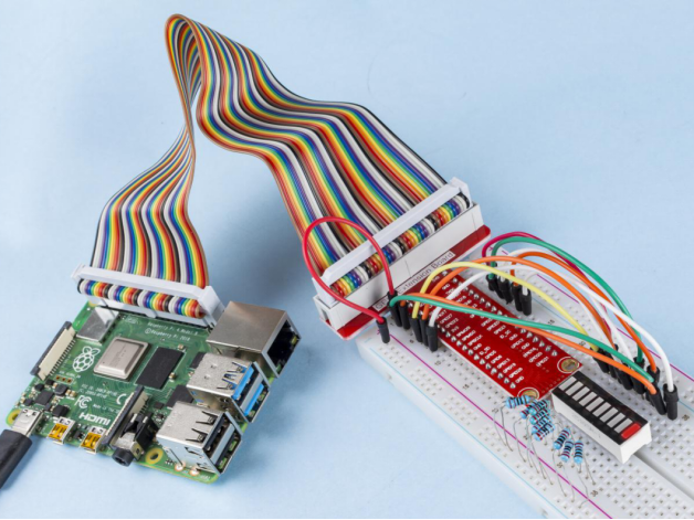
Phenomenon Picture