Introduction
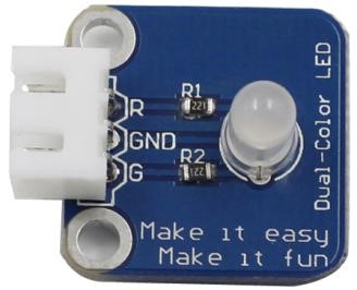
A dual-color light emitting diode (LED) is capable of emitting two different colors of light, typically red and green, rather than only one color. It is housed in a 3mm or 5mm epoxy package. It has 3 leads; common cathode or common anode is available. A dual-color LED features two LED terminals, or pins, arranged in the circuit in anti-parallel and connected by a cathode/anode. Positive voltage can be directed towards one of the LED terminals, causing that terminal to emit light of the corresponding color; when the direction of the voltage is reversed, the light of the other color is emitted. In a dual-color LED, only one of the pins can receive voltage at a time. As a result, this type of LED frequently functions as indicator lights for a variety of devices, including televisions, digital cameras, and remote controls.
Components
– 1 * Raspberry Pi
– 1 * Breadboard
– 1 * Network cable (or USB wireless network adapter)
– 1 * Dual-color LED module
– 1 * 3-pin anti-reverse cable
Experimental Principle
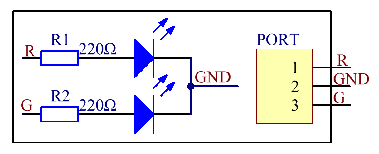
Connect pin R and G to GPIOs of Raspberry Pi, change the color of the LED from red to green by programming, and then use PWM to make it flash various mixed colors.
The schematic diagram:
Experimental Procedures
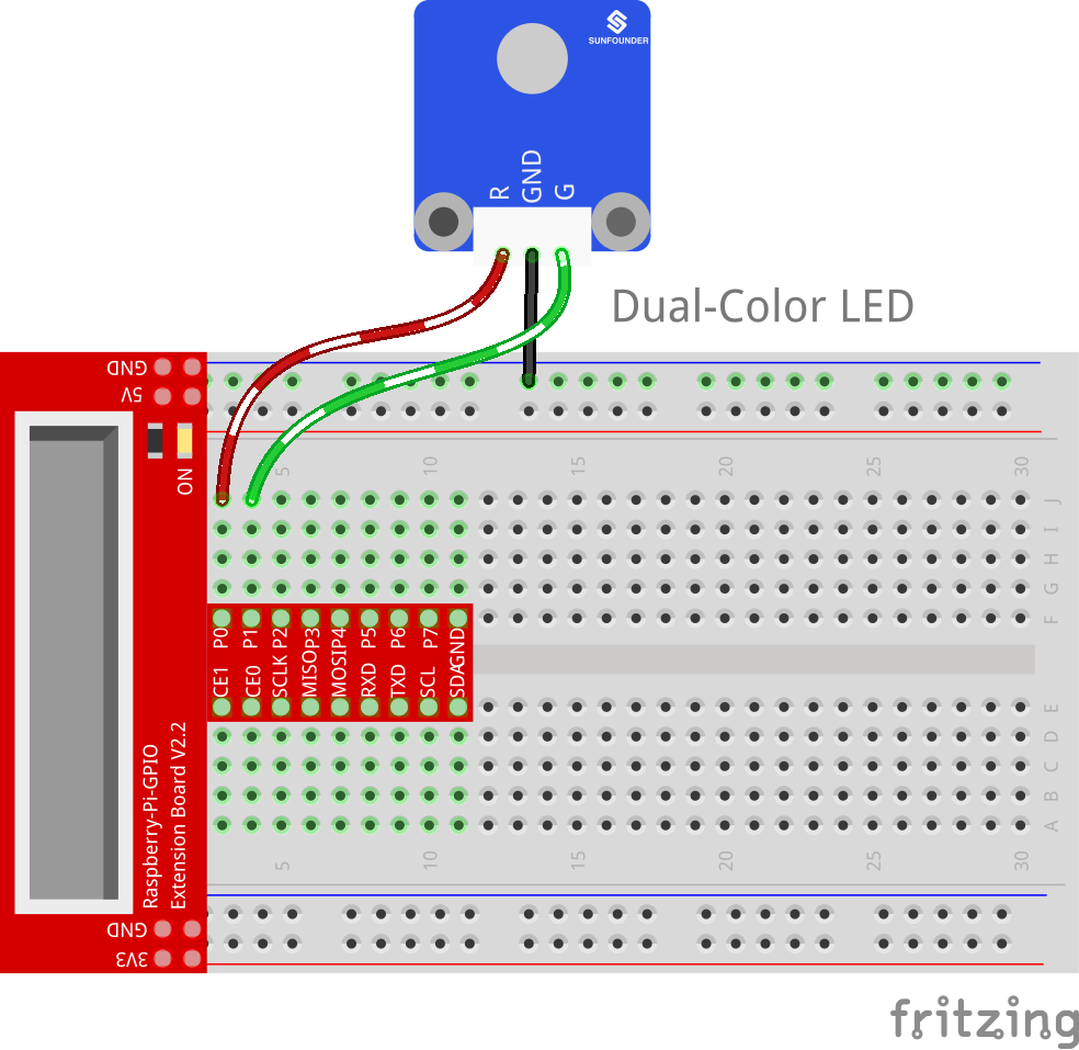
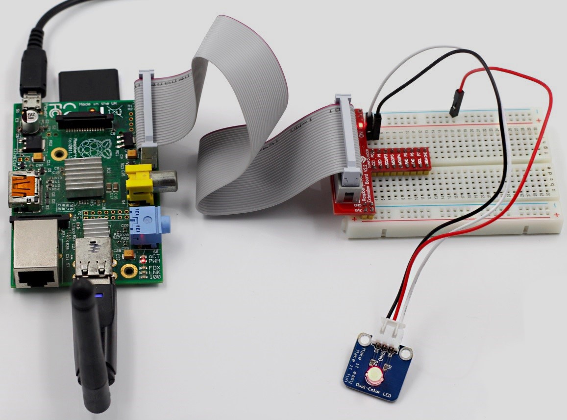
Step 1: Build the circuit
| Raspberry Pi | Dual-Color LED Module |
| GPIO0 | R |
| GND | GND |
| GPIO1 | G |
For C language users:
Step 2: Change directory
cd /home/pi/SunFounder_SensorKit_for_RPi2/C/01_dule_color_led/
Step 3: Compile
gcc dule_color_led.c –lwiringPi -lpthread
Step 4: Run
sudo ./a.out
For Python users:
Step 2: Change directory
cd /home/pi/SunFounder_SensorKit_for_RPi2/Python/
Step 3: Run
sudo python 01_dule_color_led.py
Now you can see the dual-color LED changes from red to green alternately, as well as flashing a mixed color during the alternation.
C Code
#include <wiringPi.h>
#include <softPwm.h>
#include <stdio.h>

#define uchar unsigned char

#define LedPinRed    0
#define LedPinGreen  1

void ledInit(void)
{
	softPwmCreate(LedPinRed,  0, 100);
	softPwmCreate(LedPinGreen,0, 100);
}

void ledColorSet(uchar r_val, uchar g_val)
{
	softPwmWrite(LedPinRed,   r_val);
	softPwmWrite(LedPinGreen, g_val);
}

int main(void)
{
	int i;

	if(wiringPiSetup() == -1){ //when initialize wiring failed,print messageto screen
		printf("setup wiringPi failed !");
		return 1;
	}
	//printf("linker LedPin : GPIO %d(wiringPi pin)\n",LedPin); //when initialize wiring successfully,print message to screen

	ledInit();

	while(1){
		ledColorSet(0xff,0x00);   //red
		delay(500);
		ledColorSet(0x00,0xff);   //green
		delay(500);
		ledColorSet(0xff,0x45);
		delay(500);
		ledColorSet(0xff,0xff);
		delay(500);
		ledColorSet(0x7c,0xfc);
		delay(500);
	}

	return 0;
}
Python Code
#!/usr/bin/env python
import RPi.GPIO as GPIO
import time

colors = [0xFF00, 0x00FF, 0x0FF0, 0xF00F]
pins = (11, 12)  # pins is a dict

GPIO.setmode(GPIO.BOARD)       # Numbers GPIOs by physical location
GPIO.setup(pins, GPIO.OUT)   # Set pins' mode is output
GPIO.output(pins, GPIO.LOW)  # Set pins to LOW(0V) to off led

p_R = GPIO.PWM(pins[0], 2000)  # set Frequece to 2KHz
p_G = GPIO.PWM(pins[1], 2000)

p_R.start(0)      # Initial duty Cycle = 0(leds off)
p_G.start(0)

def map(x, in_min, in_max, out_min, out_max):
	return (x - in_min) * (out_max - out_min) / (in_max - in_min) + out_min

def setColor(col):   # For example : col = 0x1122
	R_val = col  >> 8
	G_val = col & 0x00FF

	R_val = map(R_val, 0, 255, 0, 100)
	G_val = map(G_val, 0, 255, 0, 100)

	p_R.ChangeDutyCycle(R_val)     # Change duty cycle
	p_G.ChangeDutyCycle(G_val)

def loop():
	while True:
		for col in colors:
			setColor(col)
			time.sleep(0.5)

def destroy():
	p_R.stop()
	p_G.stop()
	GPIO.output(pins, GPIO.LOW)    # Turn off all leds
	GPIO.cleanup()

if __name__ == "__main__":
	try:
		loop()
	except KeyboardInterrupt:
		destroy()