Introduction
Based on the Hall Effect, a hall sensor is one that varies its output voltage in response to a magnetic field. Hall sensors are used for proximity switching, positioning, speed detection, and current sensing applications.
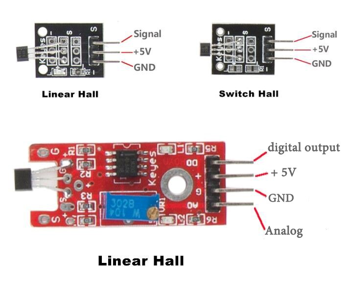
Hall sensors can be categorized into linear (analog) Hall sensors and switch Hall sensors. A switch Hall sensor consists of voltage regulator, Hall element, differential amplifier, Schmitt trigger, and output terminal and it outputs digital values. A linear Hall sensor consists of a Hall element, linear amplifier, and emitter follower and it outputs analog values.
There are three types of hall sensor module in this kit (as shown below): linear Hall sensor which outputs analog signals (in two forms), and switch Hall sensor which outputs digital signals. If you add a comparator to the linear Hall sensor, it will be able to output both analog and digital signals.
Components
– 1 * Raspberry Pi
– 1 * Breadboard
– 1 * Network cable (or USB wireless network adapter)
– 1 * Linear Hall sensor module
– 1 * Dual-color Common-Cathode LED module
– 1 * Switch Hall module
– Several jumper wires
Experimental Principle
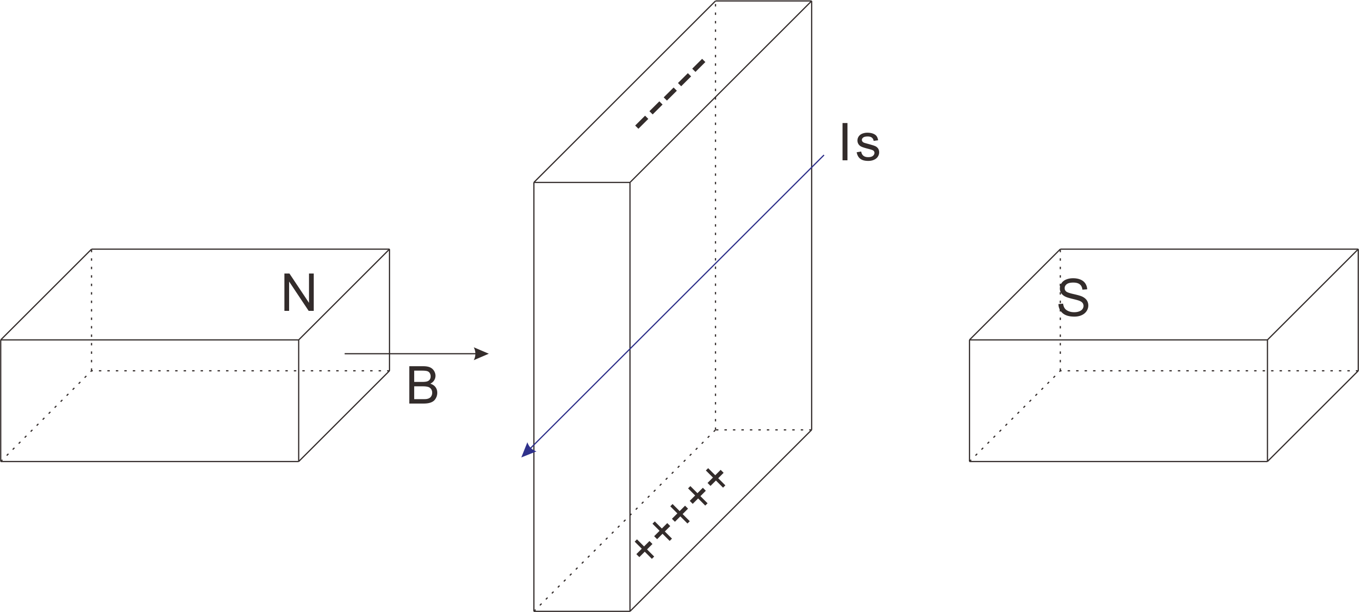
Hall Effect
Hall Effect is a kind of electromagnetic effect. It was discovered by Edwin Hall in 1879 when he was researching conductive mechanism about metals. The effect is seen when a conductor is passed through a uniform magnetic field. The natural electron drift of the charge carriers causes the magnetic field to apply a Lorentz force (the force exerted on a charged particle in an electromagnetic field) to these charge carriers. The result is what is seen as a charge separation, with a buildup of either positive or negative charges on the bottom or on the top of the plate.
Hall Sensor
A hall sensor is a kind of magnetic field sensor based on it.
Electricity carried through a conductor will produce a magnetic field that varies with current, and a Hall sensor can be used to measure the current without interrupting the circuit. Typically, the sensor is integrated with a wound core or permanent magnet that surrounds the conductor to be measured.
Experimental Procedures
For the switch Hall sensor, take the following steps.
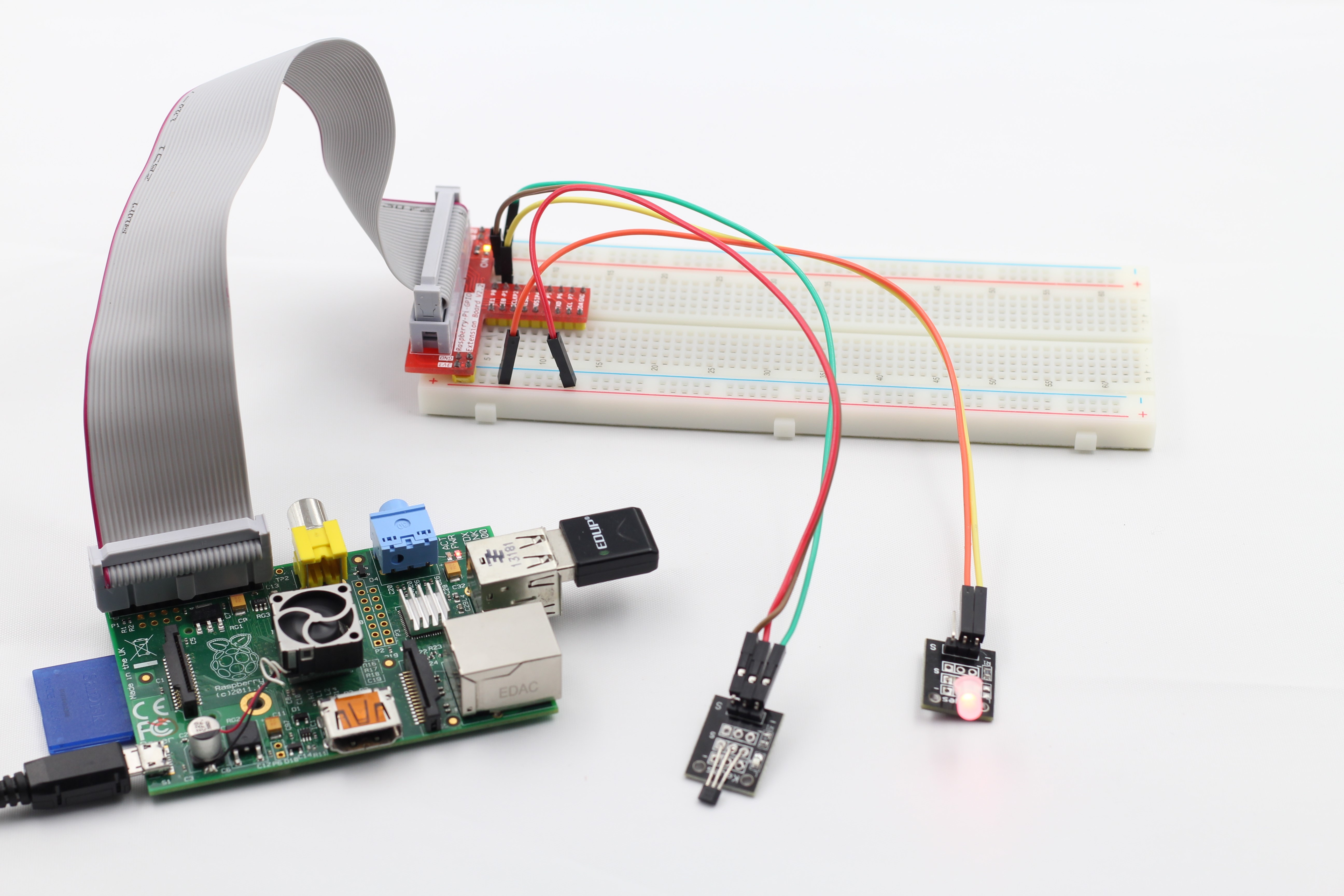
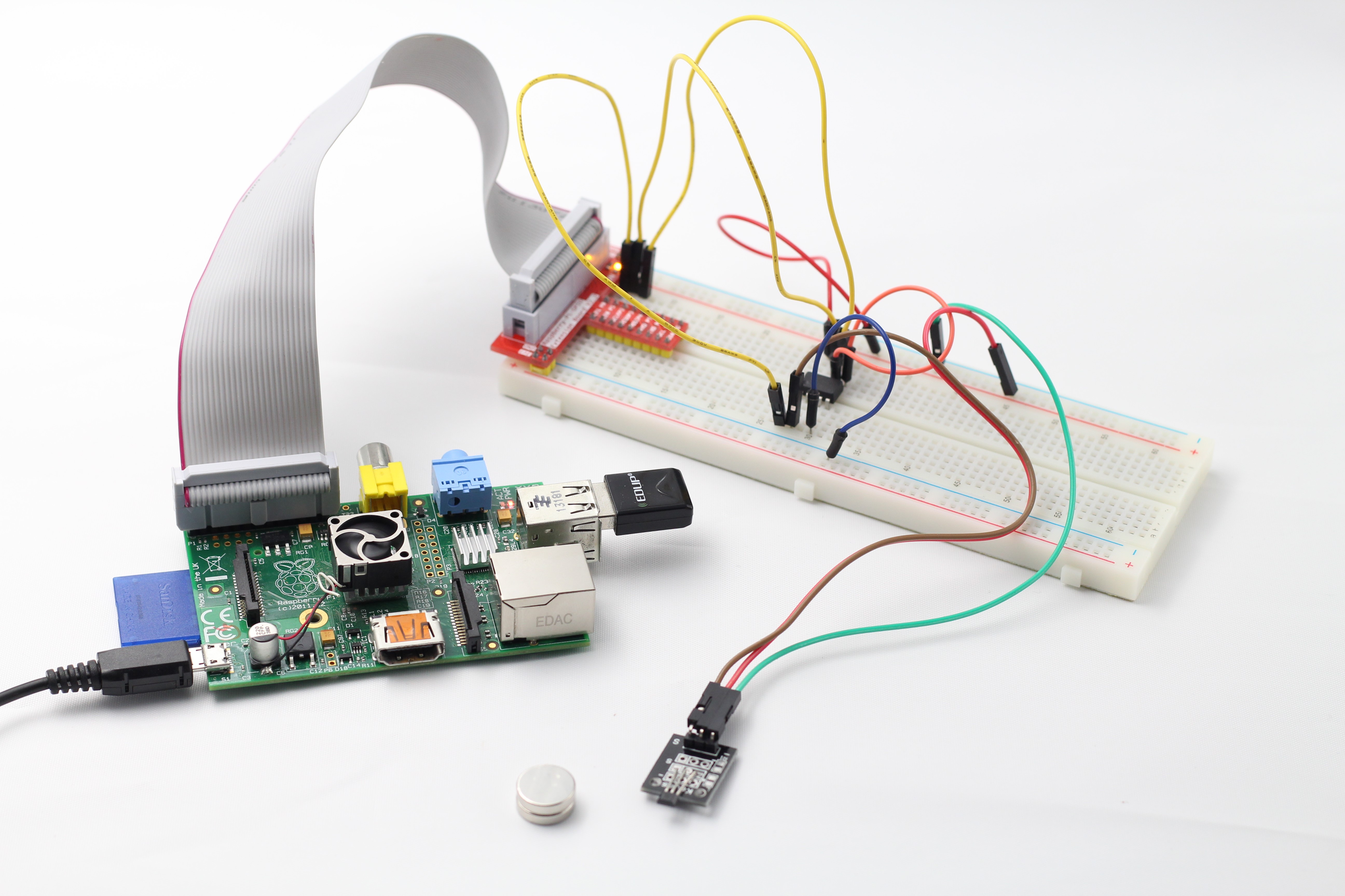
Step 1: Build the circuit
Connect GPIO0 of the Raspberry Pi to pin S of the Switch Hall Module
Connect GPIO1 of the Raspberry Pi to pin S of the Dual-Color LED Module
Connect GND of the Raspberry Pi to GND of the Switch Hall Module and GND of the Dual-Color LED Module
Connect pin 3.3V of the Raspberry Pi to pin + of the Switch Hall Module and pin + of the Dual-Color LED Module
Step 2: Edit and save the code (see path/Rpi_SensorKit_code/01_ hall/switch_hall.c)
Step 3: Compile
gcc switch_hall.c -lwiringPi
Step 4: Run
./a.out
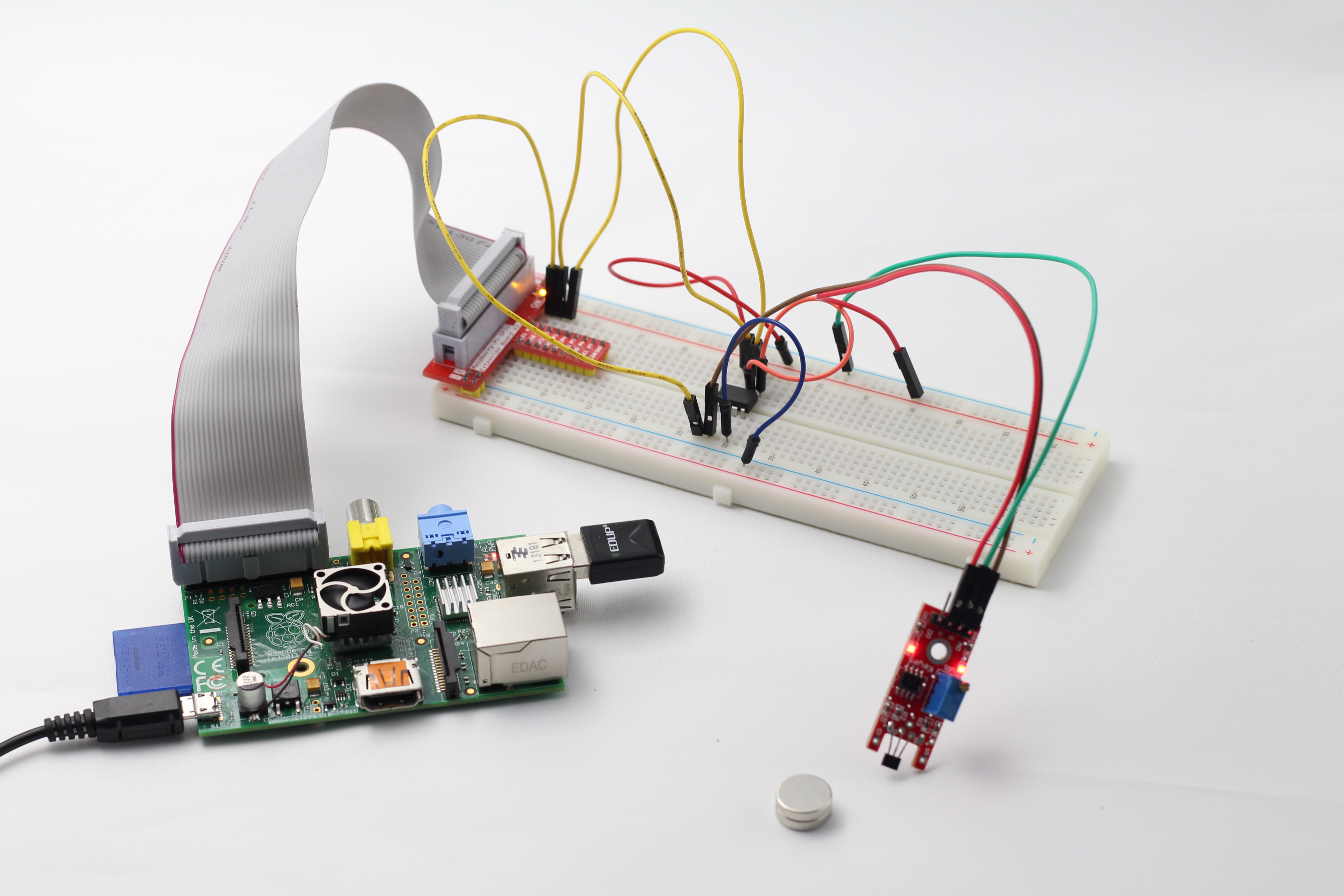
Place a magnet close to the switch Hall sensor. Then a string “Detected magnetic materials” will be printed on the screen, and the LED lights up.
switch_hall.c
#include
#include

#define HallPin    0
#define LedPin     1

int main(void)
{
	if(wiringPiSetup() == -1){ //when initialize wiring failed,print messageto screen
		printf("setup wiringPi failed !");
		return 1;
	}

	pinMode(HallPin, INPUT);
	pinMode(LedPin, OUTPUT);

	while(1){
		if(0 == digitalRead(HallPin)){
			delay(10);
			if(0 == digitalRead(HallPin)){
				while(!digitalRead(HallPin));
				digitalWrite(LedPin, !digitalRead(LedPin));
				printf("Detected magnetic materials\n");
			}
		}
	}

	return 0;
}
Python Code
#!/usr/bin/env python
import RPi.GPIO as GPIO

#Hall sensor is connected to pin 11 (BOARD-Layout!)
HALL = 11

#LED is connected to pin 12 (BOARD-Layout!)
LED  = 12

#Set pin-layout to BOARD
GPIO.setmode(GPIO.BOARD)

#Avoid error messages if GPIO was not shut down correctly before
GPIO.setwarnings(False)

#Set HALL-pin to input, use internal pull-up-resistor
GPIO.setup(HALL,GPIO.IN, pull_up_down=GPIO.PUD_UP)

#Set LED-pin to output. A resistor should be used here!
GPIO.setup(LED, GPIO.OUT)

#Turn LED off
GPIO.output(LED, GPIO.LOW)

#This function will be called if a change is detected
def change_detected(channel):
    if GPIO.input(HALL) == GPIO.LOW:
        print 'Magnetic material detected: LED on'
        GPIO.output(LED, GPIO.HIGH) #LED on
    else:
        print 'No magnetic material: LED off'
	GPIO.output(LED, GPIO.LOW) # LED off

# Register event-listener on falling and raising
# edge on HALL-sensor input. Call "change_detected" as
# callback
GPIO.add_event_detect(HALL, GPIO.BOTH, change_detected, bouncetime=25)

# The main-loop does nothing. All is done by the event-listener
try:
    while True:
        pass

# Quit on Ctrl-c
except KeyboardInterrupt:
    print "Ctrl-C - quit"

# Cleanup GPIO
finally:
    GPIO.cleanup()
For linear Hall sensor, take the following steps.
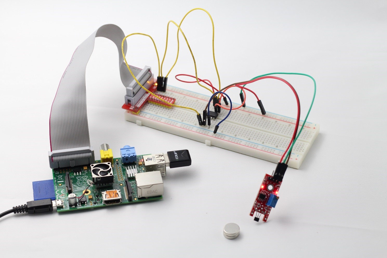
Step 1: Build the circuit
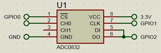
Connect pin S of the linear Hall sensor to pin CH0 of ADC0832
Step 2: Edit and save the code (see path/Rpi_SensorKit_code/02_LinearHall/linearHall.c)
Step 3: Compile
gcc linearHall.c -lwiringPi
Step 4: Run
./a.out
Place a magnet close to the linear Hall sensor and the value printed on the screen will increase.
linearHall.c
#include
#include
#include
#include
#include

#define       ADC_CS     0
#define      ADC_CLK     1
#define      ADC_DIO     2
//#define  Hall_DO_Pin     3

typedef unsigned char uchar;
typedef unsigned int uint;

uchar get_ADC_Result(void)
{
	uchar i;
	uchar dat1=0, dat2=0;

	digitalWrite(ADC_CS, 0);
	digitalWrite(ADC_CLK,0);
	digitalWrite(ADC_DIO,1);	delayMicroseconds(2);
	digitalWrite(ADC_CLK,1);	delayMicroseconds(2);

	digitalWrite(ADC_CLK,0);
	digitalWrite(ADC_DIO,1);    delayMicroseconds(2);
	digitalWrite(ADC_CLK,1);	delayMicroseconds(2);

	digitalWrite(ADC_CLK,0);
	digitalWrite(ADC_DIO,0);	delayMicroseconds(2);
	digitalWrite(ADC_CLK,1);
	digitalWrite(ADC_DIO,1);    delayMicroseconds(2);
	digitalWrite(ADC_CLK,0);
	digitalWrite(ADC_DIO,1);    delayMicroseconds(2);

	for(i=0;i<8;i++)
	{
		digitalWrite(ADC_CLK,1);	delayMicroseconds(2);
		digitalWrite(ADC_CLK,0);    delayMicroseconds(2);

		pinMode(ADC_DIO, INPUT);
		dat1=dat1<<1 | digitalRead(ADC_DIO);
	}

	for(i=0;i<8;i++)
	{
		dat2 = dat2 | ((uchar)(digitalRead(ADC_DIO))<
Python Code
#!/usr/bin/env python
import ADC0832
import time

def init():
	ADC0832.setup()

def loop():
	while True:
		res = ADC0832.getResult()
		print 'res = %d' % res
		time.sleep(0.2)

if __name__ == '__main__':
	init()
	try:
		loop()
	except KeyboardInterrupt:
		ADC0832.destroy()
		print 'The end !'
For linear Hall sensor (with a comparator), take the following steps.
Step 1: Build the circuit
Connect pin AO of the linear Hall sensor to pin CH0 of ADC0832
Step 2: Edit and save the code (see path/Rpi_SensorKit_code/03_LinearHall/linearHall.c)
Step 3: Compile
gcc linearHall.c -lwiringPi
Step 4: Run
./a.out
Put a magnet near the linear Hall sensor. The indicator light on the linear Hall sensor will brighten. At the same time, the current intensity of the magnetic field will be printed on the screen.
If you have a Raspberry Pi model B, the wiring and command are the same with model B+.
The only difference is the 26-pin T-cobbler for model B.
The case is similar for the following lessons in this kit.
linearHall.c
#include
#include
#include
#include
#include

#define     ADC_CS    0
#define     ADC_CLK   1
#define     ADC_DIO   2

typedef unsigned char uchar;
typedef unsigned int uint;

uchar get_ADC_Result(void)
{
	uchar i;
	uchar dat1=0, dat2=0;

	digitalWrite(ADC_CS, 0);
	digitalWrite(ADC_CLK,0);
	digitalWrite(ADC_DIO,1);	delayMicroseconds(2);
	digitalWrite(ADC_CLK,1);	delayMicroseconds(2);

	digitalWrite(ADC_CLK,0);
	digitalWrite(ADC_DIO,1);    delayMicroseconds(2);
	digitalWrite(ADC_CLK,1);	delayMicroseconds(2);

	digitalWrite(ADC_CLK,0);
	digitalWrite(ADC_DIO,0);	delayMicroseconds(2);
	digitalWrite(ADC_CLK,1);
	digitalWrite(ADC_DIO,1);    delayMicroseconds(2);
	digitalWrite(ADC_CLK,0);
	digitalWrite(ADC_DIO,1);    delayMicroseconds(2);

	for(i=0;i<8;i++)
	{
		digitalWrite(ADC_CLK,1);	delayMicroseconds(2);
		digitalWrite(ADC_CLK,0);    delayMicroseconds(2);

		pinMode(ADC_DIO, INPUT);
		dat1=dat1<<1 | digitalRead(ADC_DIO);
	}

	for(i=0;i<8;i++)
	{
		dat2 = dat2 | ((uchar)(digitalRead(ADC_DIO))<
Python Code
#!/usr/bin/env python
import RPi.GPIO as GPIO
import ADC0832
import time

'''
 Example how to use the hall-sensor with digital and analog output
 While the loop is printing the analog values, an interrupt-method
 is waiting for changes on the digital pin. In case of any change
 the message "change detected" is displayed.

 Example output:
 res0 = 138, res1 = 0
 res0 = 133, res1 = 0
 Change detected
 res0 = 116, res1 = 0
 Change detected
 res0 = 132, res1 = 0
 res0 = 138, res1 = 0
'''

# Digital out of sensor connected to
# pin 16 (BOAR-Layout!)
HALL = 16 #

#The ADC is connected like described in the manual


GPIO.setmode(GPIO.BOARD) # using BOARD layout

GPIO.setwarnings(False)

# Setup pins
GPIO.setup(HALL,GPIO.IN, pull_up_down=GPIO.PUD_UP)

# Callback if digital-out triggers
def change_detected(channel):
    print 'Change detected'

def init():
	ADC0832.setup()

# register event listener
GPIO.add_event_detect(HALL, GPIO.BOTH, change_detected, bouncetime=25)

def loop():
	while True:
                res0 = ADC0832.getResult(0)
		res1 = ADC0832.getResult(1)
		print 'res0 = %d, res1 = %d' % (res0,res1)
		time.sleep(0.2)

if __name__ == '__main__':
	init()
	try:
		loop()
	except KeyboardInterrupt:
		ADC0832.destroy()