Introduction
In this lesson, we will learn how to use 74HC595 to make eight LEDs blink regularly.
Components
– 1 * Raspberry Pi
– 1 * Breadboard
– 1 * 74HC595
– 8 * LED
– 8 * Resistor (220Ω)
– Jumper wires
Principle
74HC595
The 74HC595 consists of an 8−bit shift register and a storage register with three−state parallel outputs. It converts serial input into parallel output so that you can save IO ports of an MCU. The 74HC595 is widely used to indicate multipath LEDs and drive multi-bit segment displays. “Three-state” mentioned above refers to the fact that you can set the output pins as either high, low or high impedance. With data latching, the instant output will not be affected during the shifting; with data output, you can cascade 74HC595s more easily. Compatible with low voltage TTL circuit, 74HC595 can transform serial input of 8-bit data into parallel output of 8-bit data. So it is often used to extend GPIO for embedded system and drive low power devices.
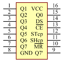
Pins of 74HC595 and their functions:
Q0-Q7: 8-bit parallel data output pins, able to control 8 LEDs or 8 pins of 7-segment display directly.
Q7’: Series output pin, connected to DS of another 74HC595 to connect multiple 74HC595s in series
MR: Reset pin, active at low level; here it is directly connected to 5V.
SH_CP: Time sequence input of shift register. On the rising edge, the data in shift register moves successively one bit, i.e. data in Q1 moves to Q2, and so forth. While on the falling edge, the data in shift register remain unchanged.
ST_CP: Time sequence input of storage register. On the rising edge, data in the shift register moves into memory register.
OE: Output enable pin, active at low level, connected to GND.
DS: Serial data input pin
VCC: Positive supply voltage
GND: Ground
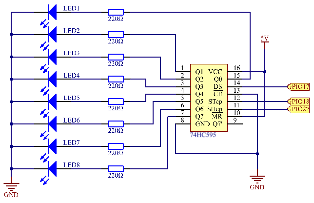
Schematic Diagram
In this experiment, connect ST_CP to Raspberry Pi GPIO18, SH_CP to GPIO27, and DS to GPIO17. Input data in DS pin to the shift register when SH_CP (the clock input of the shift register) is at the rising edge, and to the memory register when ST_CP (the clock input of the memory) is at the rising edge. Then you can control the states of SH_CP and ST_CP via Raspberry Pi GPIO to transform serial input data into parallel output data so as to save Raspberry Pi GPIOs.
Experimental Procedures
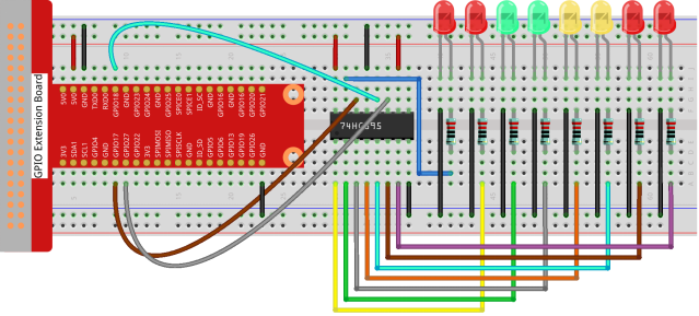
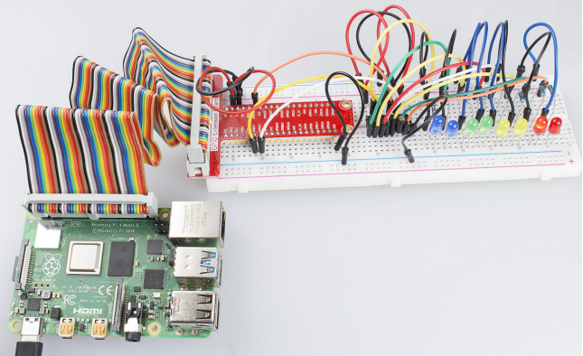
Step 1: Build the circuit.
For C Language Users:
Step 2: Change directory.
cd /home/pi/Sunfounder_SuperKit_C_code_for_RaspberryPi/10_74HC595_LED/Step 3: Compile.
gcc 74HC595_LED.c -o 74HC595_LED -lwiringPiStep 4: Run.
sudo ./74HC595_LEDFor Python Users:
Step 2: Change directory.
cd /home/pi/Sunfounder_SuperKit_Python_code_for_RaspberryPi/Step 3: Run.
sudo python3 10_74HC595_LED.pyHere you should see eight LEDs blink regularly.
Further Exploration
In this experiment, three Raspberry Pi GPIOs are used to separately control 8 LEDs based on 74HC595. In fact, 74HC595 has another powerful function – cascade. With cascade, you can use a microprocessor to control more peripherals. We’ll check more details later.