Introduction
In this lesson, we will learn to how to use L293D to drive a DC motor and make it rotate clockwise and counterclockwise. Since the DC Motor needs a larger current, for safety purpose, here we use the Power Supply Module to supply motors.
Components
– 1 * Raspberry Pi
– 1 * Breadboard
– 1 * L293D
– 1 * DC motor
– 1 * Power Module
-Jumper wires
Principle
L293D
L293D is a 4-channel motor driver integrated by chip with high voltage and high current. It’s designed to connect to standard DTL, TTL logic level, and drive inductive loads (such as relay coils, DC, stepping motors) and power switching transistors etc. DC Motors are devices that turn DC electrical energy into mechanical energy. They are widely used in electrical drive for their superior speed regulation performance.
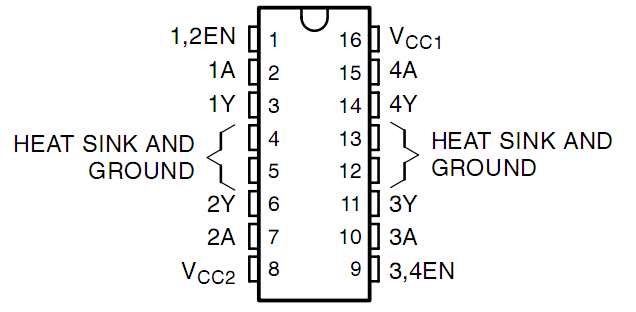
See the figure of pins below. L293D has two pins (Vcc1 and Vcc2) for power supply. Vcc2 is used to supply power for the motor, while Vcc1 to supply for the chip. Since a small-sized DC motor is used here, connect both pins to +5V. If you use a higher power motor, you need to connect Vcc2 to an external power supply.
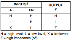
The following is the internal structure of L293D. Pin EN is an enable pin and only works with high level; A stands for input and Y for output. You can see the relationship among them at the right bottom. When pin EN is High level, if A is High, Y outputs high level; if A is Low, Y outputs Low level. When pin EN is Low level, the L293D does not work.
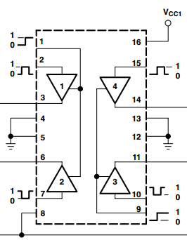
In this experiment, it just needs to drive one motor, so here only half of the L293D will be used.
DC Motor
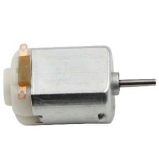
This is a 5V DC motor. It will rotate when you give the two terminals of the copper sheet one high and one low level. For convenience, you can weld the pins to it.
Size: 25*20*15MM Operation Voltage: 1-6V
Free-run current (3V): 70m A Free-run speed (3V): 13000RPM
Stall current (3V): 800mA Shaft diameter: 2mm
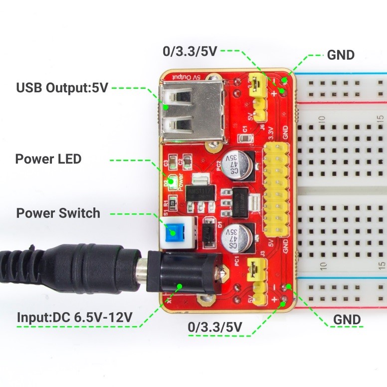
Power Supply Module
In this experiment, it needs large currents to drive the motor especially when it starts and stops, which will severely interfere with the normal work of Raspberry Pi. Therefore, we separately supply power for the motor by this module to make it run safely and steadily.
You can just plug it in the breadboard to supply power. It provides a voltage of 3.3V and 5V, and you can connect either via a jumper cap included.
Schematic diagram:
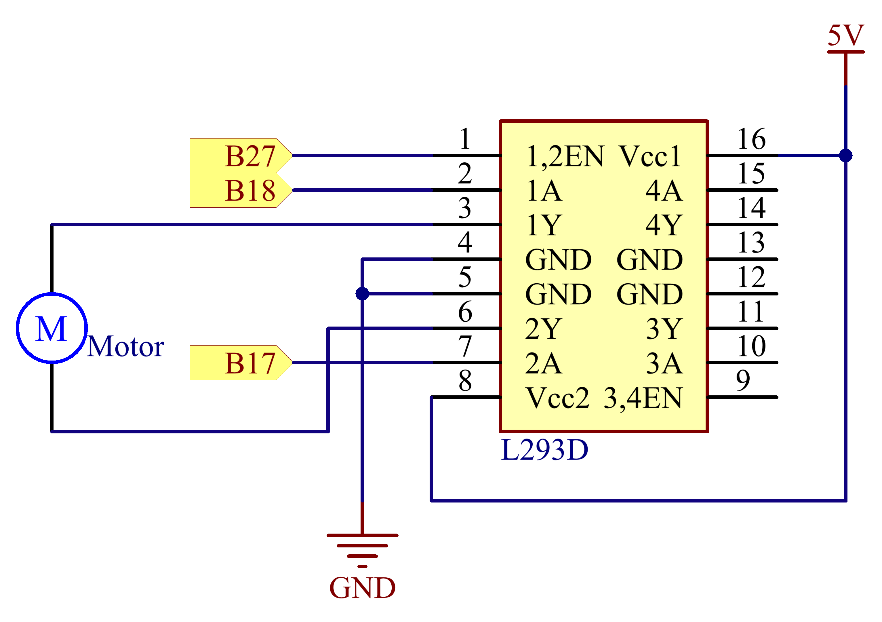
Principle: Plug the power supply module in breadboard, and insert the jumper cap to pin of 5V, then it will output voltage of 5V. Connect pin 1 of L293D to B27, and set it as high level. Connect pin2 to B18, and pin7 to B27, then set one pin high, while the other low. Thus you can change the motor’s rotation direction.
Experimental Procedures
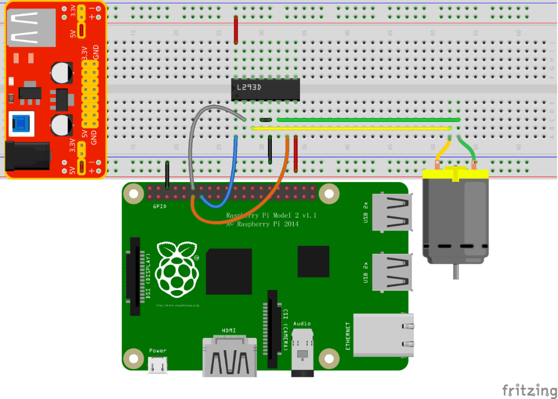
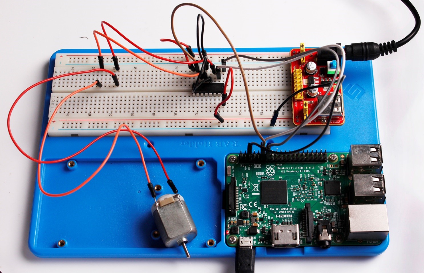
Step 1: Build the circuit. Since the power supply module and T-cable are incompatible, we will not use the T-Cable in this experiment.
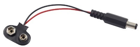
Note: The power module can apply a 9V battery with the 9V Battery Buckle in the kit. Insert the jumper cap of the power module into the 5V bus strips of the breadboard.
For C language users:
Step 2: Get into the folder of the code
cd /home/pi/SunFounder_Super_Kit_V3.0_for_Raspberry_Pi/C
Step 3: Compile
make 11_motor
Step 4: Run the executable file above.
sudo ./11_motor
For Python users:
Step 2: Get into the folder of the code
cd /home/pi/SunFounder_Super_Kit_V3.0_for_Raspberry_Pi/Python
Step 3: Run
sudo python 11_motor.py
Now, you should see the motor blade rotating.
Further Exploration
You can use buttons to control the clockwise and counterclockwise rotation of the motor blade based on the previous lessons. Also you can apply the PWM technology to control the rotation.
C Code
/**********************************************************************
* Filename    : motor.c
* Description : Controlling a motor.
* Author      : Robot
* E-mail      : support@sunfounder.com
* website     : www.sunfounder.com
* Update      : Cavon    2016/07/01
**********************************************************************/
#include <wiringPi.h>
#include <stdio.h>

#define MotorPin1		0
#define MotorPin2		1
#define MotorEnable		2

int main(void){
	int i;
	if(wiringPiSetup() == -1){ //when initialize wiring failed, print messageto screen
		printf("setup wiringPi failed !");
		return 1;
	}

	pinMode(MotorPin1, OUTPUT);
	pinMode(MotorPin2, OUTPUT);
	pinMode(MotorEnable, OUTPUT);

	printf("\n");
	printf("\n");
	printf("========================================\n");
	printf("|                Motor                 |\n");
	printf("|    ------------------------------    |\n");
	printf("|     Motor pin 1 connect to GPIO0     |\n");
	printf("|     Motor pin 2 connect to GPIO1     |\n");
	printf("|     Motor enable connect to GPIO3    |\n");
	printf("|                                      |\n");
	printf("|         Controlling a motor          |\n");
	printf("|                                      |\n");
	printf("|                            SunFounder|\n");
	printf("========================================\n");
	printf("\n");
	printf("\n");

	while(1){
		printf("Clockwise\n");
		digitalWrite(MotorEnable, HIGH);
		digitalWrite(MotorPin1, HIGH);
		digitalWrite(MotorPin2, LOW);
		for(i=0;i<3;i++){
			delay(1000);
		}

		printf("Stop\n");
		digitalWrite(MotorEnable, LOW);
		for(i=0;i)
Python Code
#!/usr/bin/env python

import RPi.GPIO as GPIO
import time

# Set up pins
MotorPin1   = 17
MotorPin2   = 18
MotorEnable = 27

def print_message():
	print ("========================================")
	print ("|                Motor                 |")
	print ("|    ------------------------------    |")
	print ("|     Motor pin 1 connect to GPIO0     |")
	print ("|     Motor pin 2 connect to GPIO1     |")
	print ("|     Motor enable connect to GPIO2    |")
	print ("|                                      |")
	print ("|         Controlling a motor          |")
	print ("|                                      |")
	print ("|                            SunFounder|")
	print ("========================================\n")
	print 'Program is running...'
	print 'Please press Ctrl+C to end the program...'
	raw_input ("Press Enter to begin\n")

def setup():
	# Set the GPIO modes to BCM Numbering
	GPIO.setmode(GPIO.BCM)
	# Set pins to output
	GPIO.setup(MotorPin1, GPIO.OUT)
	GPIO.setup(MotorPin2, GPIO.OUT)
	GPIO.setup(MotorEnable, GPIO.OUT, initial=GPIO.LOW)

# Define a motor function to spin the motor
# direction should be
# 1(clockwise), 0(stop), -1(counterclockwise)
def motor(direction):
	# Clockwise
	if direction == 1:
		# Set direction
		GPIO.output(MotorPin1, GPIO.HIGH)
		GPIO.output(MotorPin2, GPIO.LOW)
		# Enable the motor
		GPIO.output(MotorEnable, GPIO.HIGH)
		print "Clockwise"
	# Counterclockwise
	if direction == -1:
		# Set direction
		GPIO.output(MotorPin1, GPIO.LOW)
		GPIO.output(MotorPin2, GPIO.HIGH)
		# Enable the motor
		GPIO.output(MotorEnable, GPIO.HIGH)
		print "Counterclockwise"
	# Stop
	if direction == 0:
		# Disable the motor
		GPIO.output(MotorEnable, GPIO.LOW)
		print "Stop"

def main():
	print_message()
	# Define a dictionary to make the script more readable
	# CW as clockwise, CCW as counterclockwise, STOP as stop
	directions = {'CW': 1, 'CCW': -1, 'STOP': 0}
	while True:
		# Clockwise
		motor(directions['CW'])
		time.sleep(5)
		# Stop
		motor(directions['STOP'])
		time.sleep(5)
		# Anticlockwise
		motor(directions['CCW'])
		time.sleep(5)
		# Stop
		motor(directions['STOP'])
		time.sleep(5)

def destroy():
	# Stop the motor
	GPIO.output(MotorEnable, GPIO.LOW)
	# Release resource
	GPIO.cleanup()

# If run this script directly, do:
if __name__ == '__main__':
	setup()
	try:
		main()
	# When 'Ctrl+C' is pressed, the child program
	# destroy() will be executed.
	except KeyboardInterrupt:
		destroy()