Introduction
In this lesson, you will learn to how to measure light intensity using a photo resistor. The resistance of a photo resistor changes with incident light intensity. If the light intensity gets higher, the resistance decreases; if it gets lower, the resistance increases.
Components
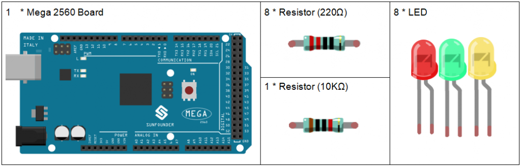
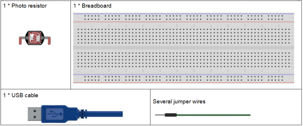
Experimental Principle
A photo resistor or photocell is a light-controlled variable resistor. The resistance of a photo resistor decreases with increasing incident light intensity; in other words, it exhibits photo conductivity. A photo resistor can be applied in light-sensitive detector circuits, and light- and darkness-activated switching circuits.
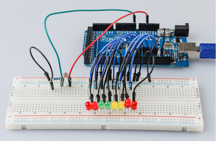
In this experiment, we will use 8 Eds to show the light intensity. The higher the light intensity is, the more Eds will light up. When the light intensity is high enough, all the Eds will be on. When there is no light, all the Eds will go out.
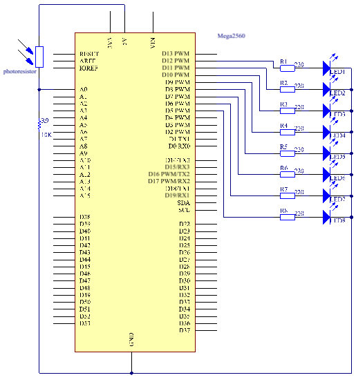
The schematic diagram:
Experimental Procedures
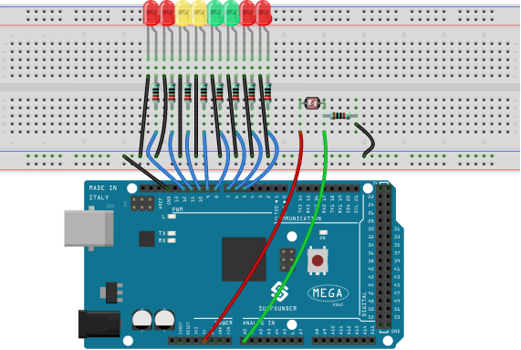
Step 1: Build the circuit
Step 2: Open the code file.
Step 3: Select the Board and Port.
Step 4: Upload the sketch to the board.
Now, shine some light on the photo resistor, and you will see several Eds light up. Shine more light and you will see more Eds light up. When you place it in a dark environment, all the Eds will go out.
Code Analysis
Code Analysis 11-1 Set the variables
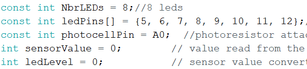
The 8 Eds are connected to pin5-pin12, in this code, use a array to store the pins, ledPins[0] is equal to 5, ledPins[1] to 6 and so on.
Code Analysis 11–2 Set 8 pins to OUTPUT
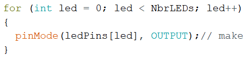
Using the for() statement set the 8 pins to OUTPUT. The variable led is added from 0 to 8, and the pinMode() function sets pin5 to pin12 to OUTPUT in turn.
Code Analysis 11–3 Read the analog value of the photoresistor

Read the analog value of the photocellPin(A0) and store to the variable sensorValue.
analogRead(): Reads the value from the specified analog pin. Arduino boards contain a multichannel, 10-bit analog to digital converter. This means that it will map input voltages between 0 and the operating voltage(5V or 3.3V) into integer values between 0 and 1023.
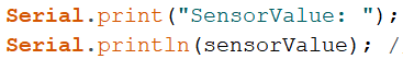
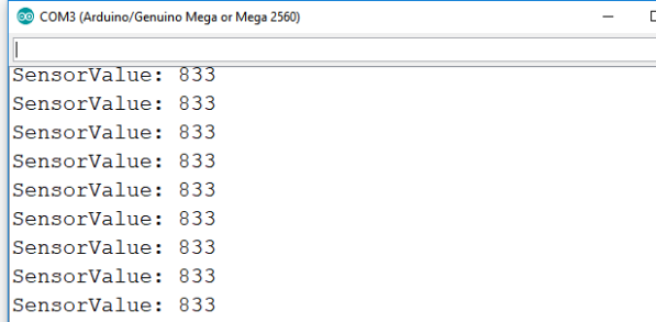
Use the Serial.print()function to print the analog value of the photoresistor. You can see them on the Serial Monitor.
Serial.print():Prints data to the serial port as human-readable ASCII text. This command can take many forms. Numbers are printed using an ASCII character for each digit. Floats are similarly printed as ASCII digits, defaulting to two decimal places. Bytes are sent as a single character. Characters and strings are sent as is.
Serial.println(): Thiscommand takes the same forms as Serial.print(), but it is followed by a carriage return character (ASCII 13, or ‘\r’) and a newline character (ASCII 10, or ‘\n’).
Code Analysis 11–4 Map the analog value to 8 LEDs
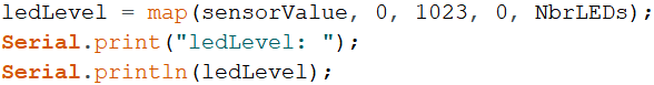
The map() command is used to map 0-1023 to 0-NbrLEDs(8), (1023-0)/(8-0)=127.875
| 0-127.875 | 128-255.75 | 256-383.625 | 384-511.5 | 512-639.375 | 640-767.25 | 768-895.125 | 896-1023 |
| 0 | 1 | 2 | 3 | 4 | 5 | 6 | 7 |
If sensorValue is 560, then the ledLevel is 4.
map(value, fromLow, fromHigh, toLow, toHigh) re-maps a number from one range to another. That is, a value of fromLow would get mapped to one of toLow, and a value of fromHigh to one of toHigh, values in-between to values in-between, etc.
Code Analysis 11–5 Light up the LEDs
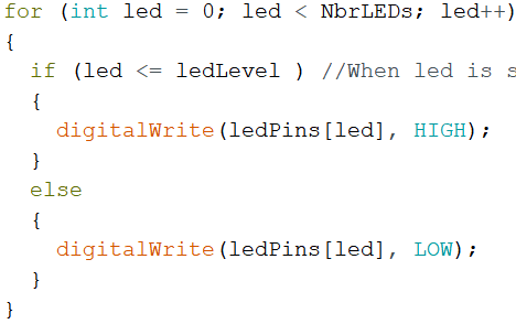
Light up the corresponding LEDs. Such as, when the ledLevel is 4, then light up the ledPins[0] to ledPins[4] and go out the ledPins[5] to ledPins[7].