Introduction
In this lesson, we will use light intensity to control the luminance of an LED. When the light gets stronger, the LED will get brighter. When the light gets weaker, the LED will get darker.
Components
– 1*Raspberry Pi
– 1*Breadboard
– 1*Network cable (or USB wireless network adapter)
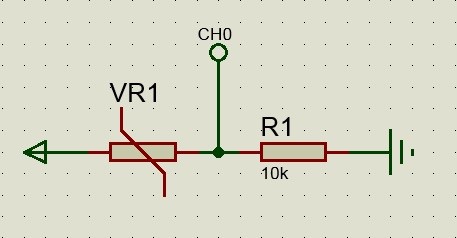
– 1*Photoresistor
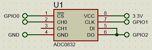
– 1*ADC0832
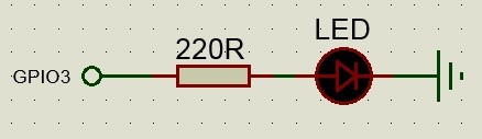
– 1*LED
– 1*Resistor (220Ω)
– 1*Resistor (10KΩ)
-Jumper wires
Experimental Principle
In this experiment, we use PWM to control the luminance of the LED. The greater the duty cycle is, the brighter the LED is.
The resistance of the photoresistor decreases when the light intensity increases. We use the photoresistor output as the parameter of PWM after simple calculation by ADC. The weaker the light intensity is, the greater the PWM duty cycle is, and the brighter the LED is.
Experimental Procedures
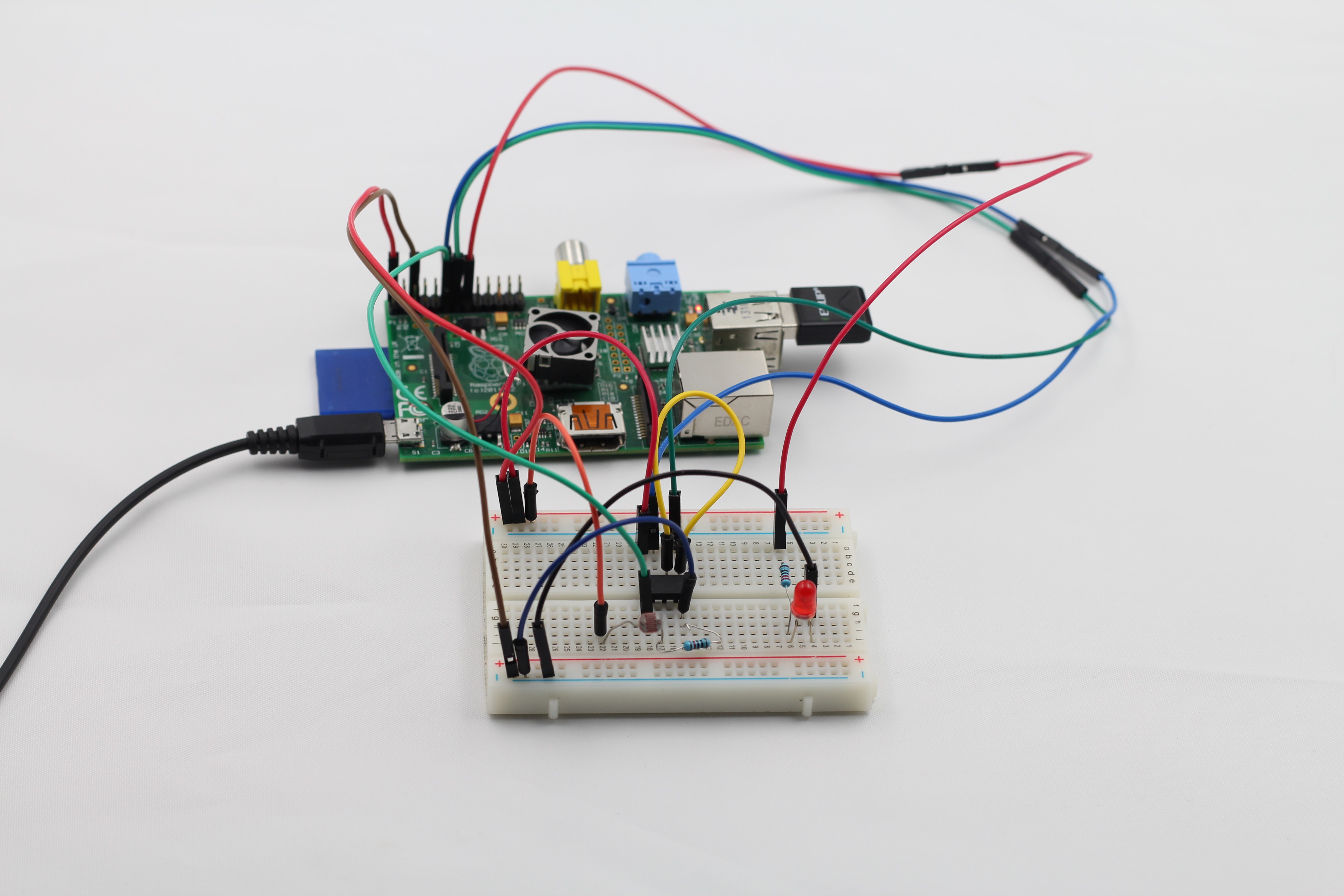
Step 1: Connect the circuit
Step 2: Edit and save the code(see path/Rpi_UniversalStartKit /12_illumCtrl/illumCtrl.c)
Step 3: Compile the code
gcc illumCtrl.c -lwiringPi -lpthread
Step 4: Run the program
./a.out
Press Enter, if you change the incident light intensity, you will see the luminance of the LED change accordingly.
C Code
#include <wiringPi.h>
#include <softPwm.h>
#include <stdio.h>

typedef unsigned char uchar;
typedef unsigned int  uint;

#define     ADC_CS    0
#define     ADC_CLK   1
#define     ADC_DIO   2

#define        LED    3

uchar get_ADC_Result(void)
{
 //10:CH0
 //11:CH1
 uchar i;
 uchar dat1=0, dat2=0;

 digitalWrite(ADC_CS, 0);

 digitalWrite(ADC_CLK,0);
 digitalWrite(ADC_DIO,1); delayMicroseconds(2);
 digitalWrite(ADC_CLK,1); delayMicroseconds(2);
 digitalWrite(ADC_CLK,0);

 digitalWrite(ADC_DIO,1);    delayMicroseconds(2); //CH0 10
 digitalWrite(ADC_CLK,1); delayMicroseconds(2);
 digitalWrite(ADC_CLK,0);

 digitalWrite(ADC_DIO,0); delayMicroseconds(2); //CH0 0

 digitalWrite(ADC_CLK,1);
 digitalWrite(ADC_DIO,1);    delayMicroseconds(2);
 digitalWrite(ADC_CLK,0);
 digitalWrite(ADC_DIO,1);    delayMicroseconds(2);

 for(i=0;i<8;i++)
 {
  digitalWrite(ADC_CLK,1); delayMicroseconds(2);
  digitalWrite(ADC_CLK,0);    delayMicroseconds(2);

  pinMode(ADC_DIO, INPUT);
  dat1=dat1<<1 | digitalRead(ADC_DIO);
 }

 for(i=0;i<8;i++)
 {
  dat2 = dat2 | ((uchar)(digitalRead(ADC_DIO))<<i);
  digitalWrite(ADC_CLK,1);  delayMicroseconds(2);
  digitalWrite(ADC_CLK,0);    delayMicroseconds(2);
 }

 digitalWrite(ADC_CS,1);

 pinMode(ADC_DIO, OUTPUT);

 return(dat1==dat2) ? dat1 : 0;
}

int main(void)
{
 uchar adcVal;

 if(wiringPiSetup() == -1){
  printf("setup wiringPi failed !");
  return 1;
 }

 pinMode(ADC_CS,  OUTPUT);
 pinMode(ADC_CLK, OUTPUT);

 softPwmCreate(LED, 0, 100);

 while(1){
  pinMode(ADC_DIO, OUTPUT);
  adcVal = get_ADC_Result();
  softPwmWrite(LED, 200 - adcVal);
 }

 return 0;
}
Python Code
#!/usr/bin/env python
import RPi.GPIO as GPIO
import ADC0832

LedPin = 15

def printMsg():
 print 'Press Ctrl+C to end the program...'

def adcInit():
 ADC0832.setup()

def ledInit():
 GPIO.setmode(GPIO.BOARD)
 GPIO.setup(LedPin, GPIO.OUT)
 GPIO.output(LedPin, GPIO.LOW)  # led off

def loop():
 p = GPIO.PWM(LedPin, 1000) # Set PWM Frequence to 1000Hz
 p.start(0)
 while True:
  res = ADC0832.getResult()
  if res > 100:
   res = 100
  p.ChangeDutyCycle(res)   # Change the duty cycle according to res

if __name__ == '__main__':
 printMsg()
 adcInit()
 ledInit()
 try:
  loop()
 except KeyboardInterrupt:
  ADC0832.destroy()
  print 'The end !'