Introduction
With low-voltage scanning, dot-matrix LED displays have advantages such as power saving, long service life, low cost, high brightness, wide angle of view, long visual range, waterproof, and numerous specifications. Dot-matrix LED displays can meet the needs of different applications and thus have a broad development prospect. This time, we will conduct an LED dot-matrix experiment to experience its charm firsthand.
Components
– 1 * SunFounder Uno board
– 1 * 8*8 dot-matrix
– 8 * Resistor (220Ω)
– 1 * Breadboard
– Jumper wires
– 2 * 74HC595
– 1 * USB cable
Principle
The external view of a dot-matrix is shown as follow:
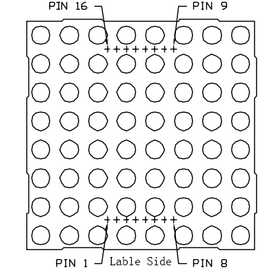
For pin definition:
Define row and column numbering at first (only for a dot-matrix whose model number ends with BS)
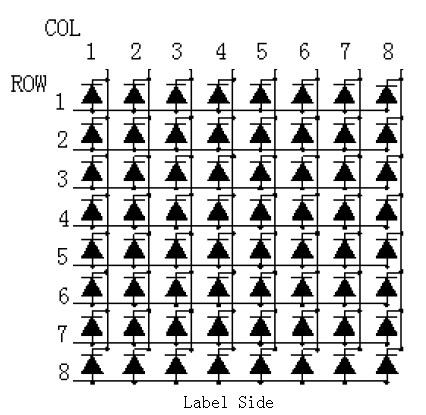
Pin numbering corresponding to the above rows and columns:
| COL | 1 | 2 | 3 | 4 | 5 | 6 | 7 | 8 |
| Pin No. | 13 | 3 | 4 | 10 | 6 | 11 | 15 | 16 |
| ROW | 1 | 2 | 3 | 4 | 5 | 6 | 7 | 8 |
| Pin No. | 9 | 14 | 8 | 12 | 1 | 7 | 2 | 5 |
The display principle of the 8*8 dot-matrix:
The 8*8 dot-matrix is made up of sixty-four LEDs and each LED is placed at the cross point of a row and a column. When the electrical level of a certain row is High and the electrical level of a certain column is Low, then the corresponding LED will light up; if you want to light the LED on the first dot, you should set ROW 1 to high level and COL 1 to low level, then the LED on the first dot will light up; if you want to light the LEDs on the first row, you should set ROW 1 to high level and COL (1, 2, 3, 4, 5, 6, 7, 8) to low level, then all the LEDs on the first row will light up; if you want to light the LEDs on the first column, you should set COL 1 to low level and ROW (1, 2, 3, 4, 5, 6, 7, 8) to high level, then all the LEDs on the first column will light up.
The principle of 74HC595 has been previously illustrated. One chip is used to control the rows of the dot-matrix while the other is to control the columns.
Experimental Procedures
Step 1: Build the circuit
Connect 74HC595 (u2), Dot-Matrix and SunFounder Uno board
| 74HC595 (u2) | Dot-Matrix | SunFounder Uno |
| Q1(Pin1) | 2 | |
| Q2 (Pin2) | 7 | |
| Q3(Pin3) | 1 | |
| Q4(Pin4) | 12 | |
| Q5(Pin5) | 8 | |
| Q6(Pin6) | 14 | |
| Q7(Pin7) | 9 | |
| GND(Pin8) | GND | |
| Q7’ (Pin9) | ||
| MR(Pin10) | 5V | |
| SH_cp(Pin11) | 12 | |
| ST_cp(Pin12) | 8 | |
| CE(Pin13) | GND | |
| DS(Pin14) connected to Q7’ of 74HC595(u3) | ||
| Q0(Pin15) | 5 | |
| VCC(Pin16) | 5V |
Connect the other 74HC595 (u3), Dot-Matrix and SunFounder Uno board
| 74HC595(u3) | Dot-Matrix | SunFounder Uno |
| Q1(Pin1) | 3 | |
| Q2 (Pin2) | 4 | |
| Q3(Pin3) | 10 | |
| Q4(Pin4) | 6 | |
| Q5(Pin5) | 11 | |
| Q6(Pin6) | 15 | |
| Q7(Pin7) | 16 | |
| GND(Pin8) | GND | |
| Q7’(Pin9) connected to DS of 74HC595(u2) | ||
| MR(Pin10) | 5V | |
| SH_cp(Pin11) | 12 | |
| ST_cp(Pin12) | 8 | |
| CE(Pin13) | GND | |
| DS(Pin14) | 11 | |
| Q0(Pin15) | 13 | |
| VCC(Pin16) | 5V |
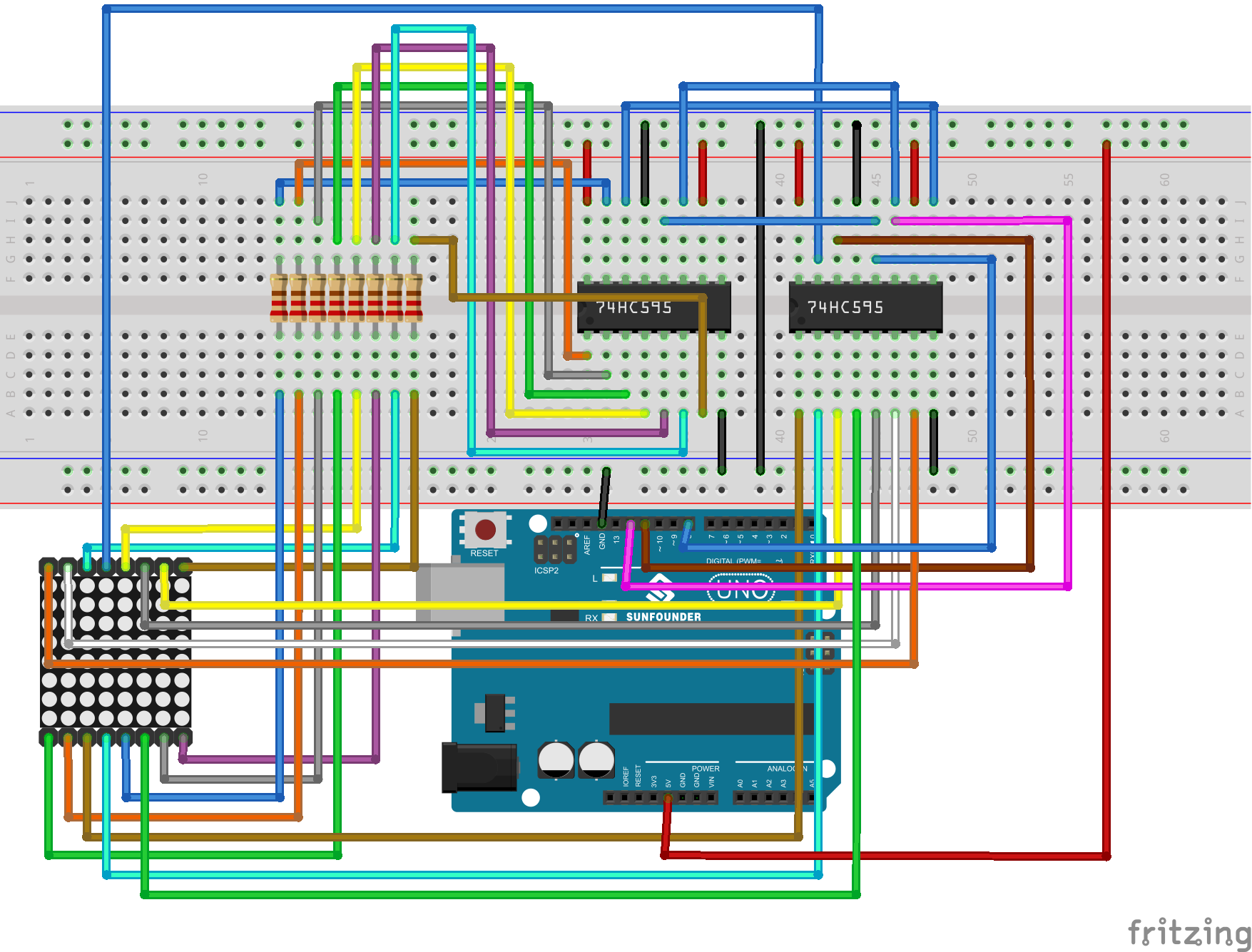
The schematic diagram
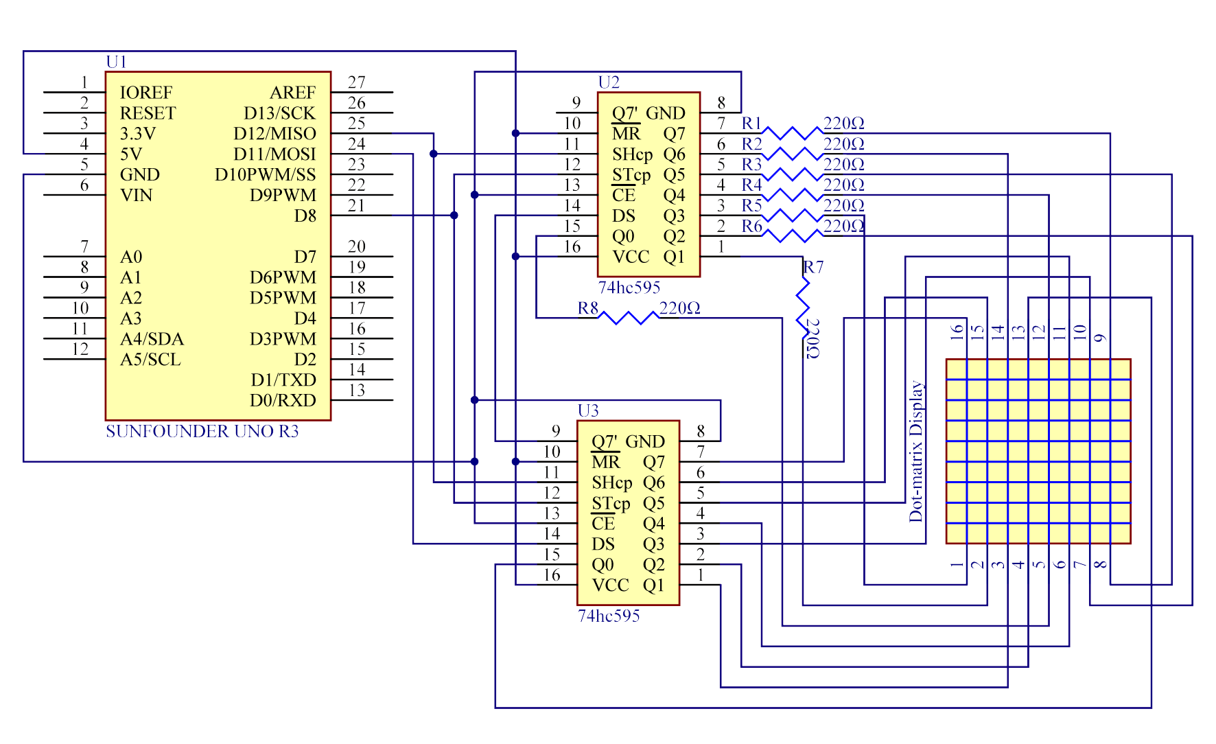
Step 2: Program (please go to our official website www.sunfounder.com to download related code by clicking LEARN -> Get Tutorials)
Step 3: Compile the code
Step 4: Upload the sketch to the SunFounder Uno board
Here you should see the dot-matrix display 0 to F circularly.
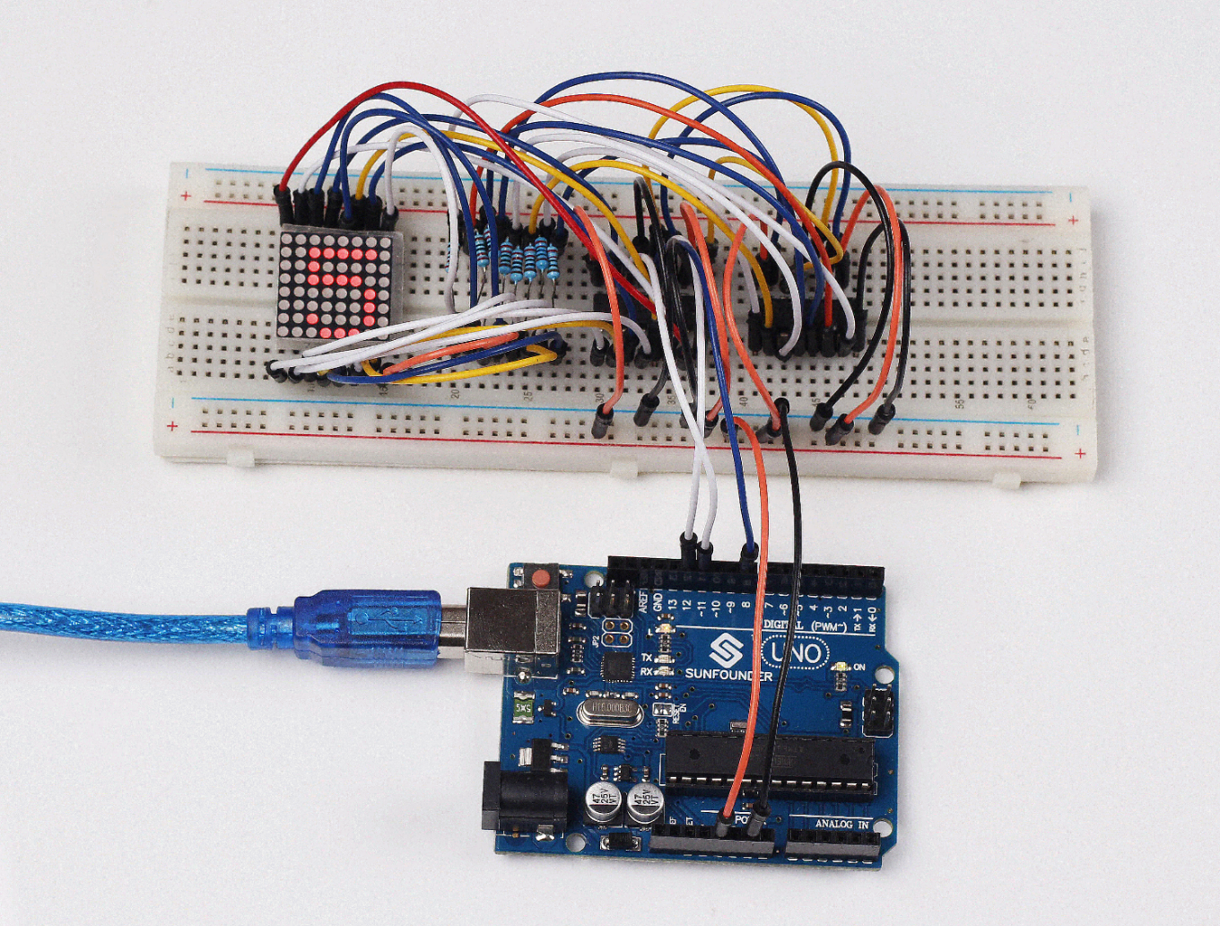
Code
| //Dot-Matrix Display //The dot-matrix will display 0 to F circularly //Email:support@sunfounder.com //Website:www.sunfounder.com //2015.5.7 const int latchPin = 8;//Pin connected to ST_CP of 74HC595 const int clockPin = 12;//Pin connected to SH_CP of 74HC595 const int dataPin = 11; //Pin connected to DS of 74HC595 int data[] = { 0xFF,0xFF,0xFF,0xFF,0xFF,0xFF,0xFF,0xFF,/*” “,0*/ 0xFF,0xC1,0xBE,0xBE,0xBE,0xC1,0xFF,0xFF,/*”0″,1*/ 0xFF,0xDF,0xDF,0x80,0xFF,0xFF,0xFF,0xFF,/*”1″,2*/ 0xFF,0xDC,0xBC,0xBA,0xB6,0xCE,0xFF,0xFF,/*”2″,3*/ 0xFF,0xDD,0xBE,0xB6,0xB6,0xC9,0xFF,0xFF,/*”3″,4*/ 0xFB,0xF3,0xEB,0xDB,0x80,0xFB,0xFF,0xFF,/*”4″,5*/ 0xFF,0x8D,0xAE,0xAE,0xAE,0xB1,0xFF,0xFF,/*”5″,6*/ 0xFF,0xC1,0x96,0xB6,0xB6,0xD9,0xFF,0xFF,/*”6″,7*/ 0xFF,0xBF,0xBC,0xB3,0xAF,0x9F,0xFF,0xFF,/*”7″,8*/ 0xFF,0xC9,0xB6,0xB6,0xB6,0xC9,0xFF,0xFF,/*”8″,9*/ 0xFF,0xCD,0xB6,0xB6,0xB4,0xC1,0xFF,0xFF,/*”9″,10*/ 0xFC,0xF3,0xCB,0x9B,0xEB,0xF3,0xFC,0xFF,/*”A”,11*/ 0xFF,0x80,0xB6,0xB6,0xB6,0xB6,0xC9,0xFF,/*”B”,12*/ 0xFF,0xE3,0xDD,0xBE,0xBE,0xBE,0xBE,0xDD,/*”C”,13*/ 0xFF,0x80,0xBE,0xBE,0xBE,0xBE,0xDD,0xE3,/*”D”,14*/ 0xFF,0x80,0xB6,0xB6,0xB6,0xB6,0xBE,0xFF,/*”E”,15*/ 0xFF,0x80,0xB7,0xB7,0xB7,0xB7,0xBF,0xFF,/*”F”,16*/ 0xFF,0xFF,0xFF,0xFF,0xFF,0xFF,0xFF,0xFF,/*” “,17*/ }; void setup () { //set pins to output pinMode(latchPin,OUTPUT); pinMode(clockPin,OUTPUT); pinMode(dataPin,OUTPUT); } void loop() { for(int n = 0; n < 136; n++) { for(int t = 0;t < 10;t ++)//Show repeated 10 times { int dat = 0x01; for(int num = n; num < 8+n; num++) { shiftOut(dataPin,clockPin,MSBFIRST,~data[num]);//control ROW of dot matrix shiftOut(dataPin,clockPin,MSBFIRST,~dat); //control COL of dot matrix //return the latch pin high to signal chip that it //no longer needs to listen for information digitalWrite(latchPin,HIGH); //pull the latchPin to save the data //delay(1); //wait for a microsecond digitalWrite(latchPin,LOW); //ground latchPin and hold low for as long as you are transmitting dat = dat<<1; delay(1); //wait for a microsecond } } } } |
Video
