Introduction
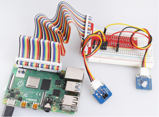
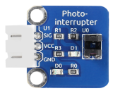
A photo-interrupter (as shown below) is a sensor with a light-emitting component and light-receiving component packaged and placed on face-to-face. It applies the principle that light is interrupted when an object passes through the sensor. Therefore, photo-interrupters are widely used in speed measurement.
Required Components
– 1 * Raspberry Pi
– 1 * Breadboard
– 1 * Dual-color LED module
– 1 * Photo-interrupter module
– 2 * 3-Pin anti-reverse cable
Experimental Principle
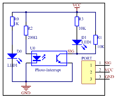
Basically a photo-interrupter consists of two parts: transmitter and receiver. The transmitter (e.g., an LED or a laser) emits light and then the light goes to the receiver. If that light beam between the transmitter and receiver is interrupted by an obstacle, the receiver will detect no incident light even for a moment and the output level will change. In this experiment, we will turn an LED on or off by using this change. The schematic diagram:
Experimental Procedures
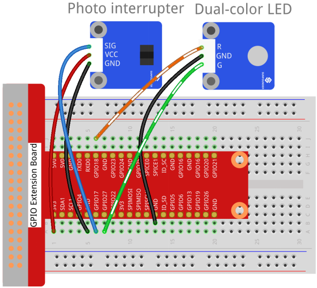
Step 1: Build the circuit.
| Raspberry Pi | GPIO Extension Board | Photo-interrupter Module |
| GPIO0 | GPIO17 | SIG |
| 3.3V | 3V3 | VCC |
| GND | GND | GND |
| Raspberry Pi | GPIO Extension Board | Dual-color LED Module |
| GPIO1 | GPIO18 | R |
| GND | GND | GND |
| GPIO2 | GPIO27 | G |
For C Users:
Step 2: Change directory.
cd /home/pi/SunFounder_SensorKit_for_RPi2/C/12_photo_interrupter/Step 3: Compile.
gcc photo_interrupter.c -lwiringPiStep 4: Run.
sudo ./a.outFor Python Users:
Step 2: Change directory.
cd /home/pi/SunFounder_SensorKit_for_RPi2/Python/Step 3: Run.
sudo python3 12_photo_interrupter.pyNow the LED will light up green. Stick a piece of paper in the gap of photo interrupter. Then “Light was blocked” will be printed on the screen and the LED will flash red. Remove the paper, and the LED will turn green again.