Introduction
In this lesson, we will learn how to use 74HC595 to make eight LEDs blink regularly.
Components
– 1 * Raspberry Pi
– 1 * Breadboard
– 1 * 74HC595
– 8 * LED
– 8 * Resistor (220Ω)
– Jumper wires
Principle
74HC595
The 74HC595 consists of an 8−bit shift register and a storage register with three−state parallel outputs. It converts serial input into parallel output so that you can save IO ports of an MCU. The 74HC595 is widely used to indicate multipath LEDs and drive multi-bit segment displays. “Three-state” mentioned above refers to the fact that you can set the output pins as either high, low or high impedance. With data latching, the instant output will not be affected during the shifting; with data output, you can cascade 74HC595s more easily. Compatible with low voltage TTL circuit, 74HC595 can transform serial input of 8-bit data into parallel output of 8-bit data. So it is often used to extend GPIO for embedded system and drive low power devices.
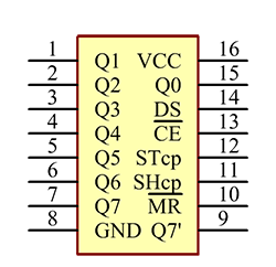
Pins of 74HC595 and their functions:
Q0-Q7: 8-bit parallel data output pins, able to control 8 LEDs or 8 pins of 7-segment display directly.
Q7’: Series output pin, connected to DS of another 74HC595 to connect multiple 74HC595s in series
MR: Reset pin, active at low level; here it is directly connected to 5V to keep the chip from resetting.
SH_CP: Time sequence input of shift register. On the rising edge, the data in shift register moves successively one bit, i.e. data in Q1 moves to Q2, and so forth. While on the falling edge, the data in shift register remain unchanged.
ST_CP: Time sequence input of storage register. On the rising edge, data in the shift register moves into memory register.
OE: Output enable pin, active at low level; here connected to GND to keep 74HC595 in output enable state.
DS: Serial data input pin
VCC: Positive supply voltage
GND: Ground
The schematic diagram is shown as below:
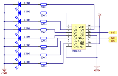
Principle: In this experiment, connect 74HC595’s ST_CP to Raspberry Pi’s B18, SH_CP to B27, and DS to B17; connect a current-limit resistor and then a LED to Q0-Q7 respectively; connect MR and VCC to 5V, CE and GND to GND. Input data in DS pin to the shift register when SH_CP (the clock input of the shift register) is at the rising edge, and to the memory register when ST_CP (the clock input of the memory) is at the rising edge, and output to Q0-Q7. Then you can control the states of SH_CP and ST_CP via Raspberry Pi GPIO to transform serial input data into parallel output data so as to save Raspberry Pi GPIOs.
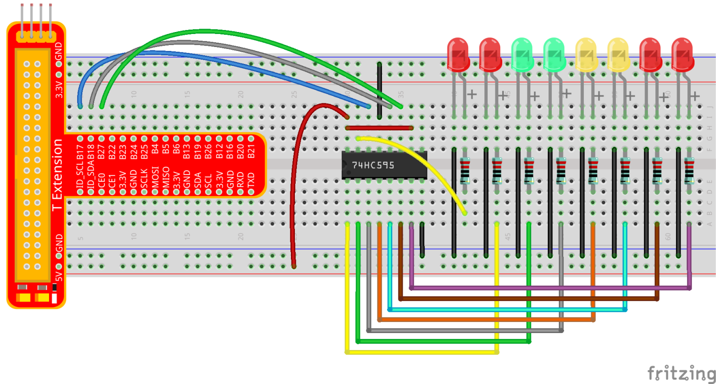
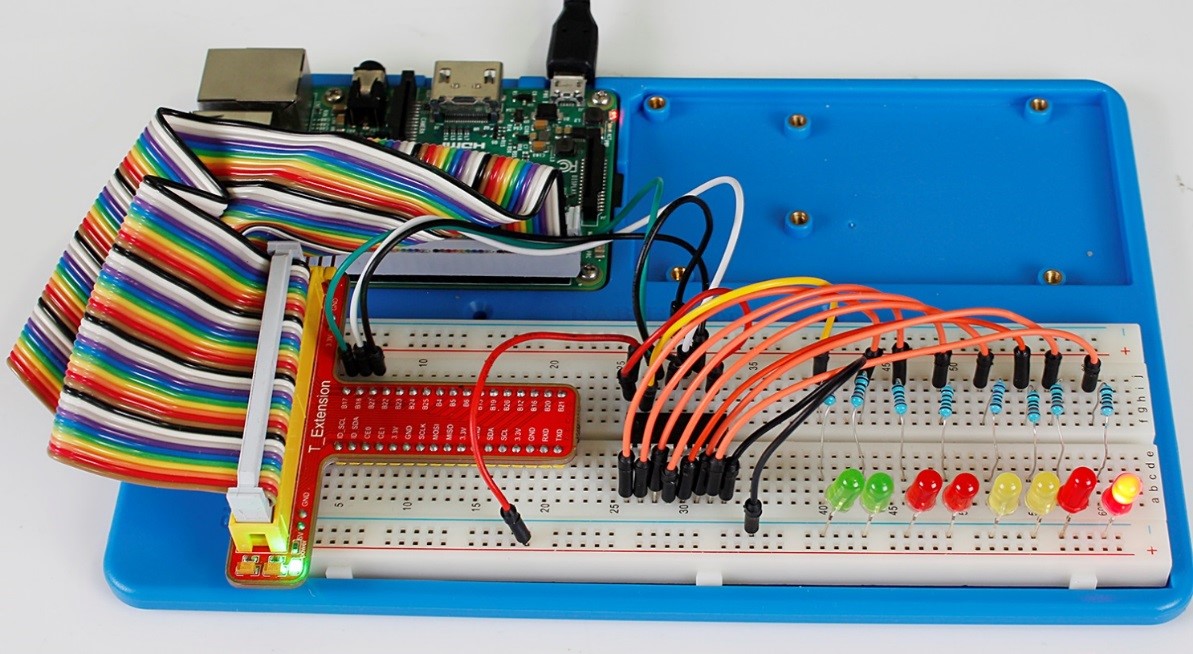
Experimental Procedures
Step 1: Build the circuit. If you want to take out the chip from the breadboard, DO NOT pull it in one direction forcefully, for fear that the pins on it may be bent and you may get hurt. Try to use a sharp tool to cross the notch of the breadboard to remove the chip.
For C language users:
Step 2: Get into the folder of the code.
cd /home/pi/SunFounder_Super_Kit_V3.0_for_Raspberry_Pi/C
Step 3: Compile
make 13_74HC595_LED
Step 4: Run the executable file above.
sudo ./13_74HC595_LED
Sketch in later part not explained here is to light up 8 LEDs together, and dim them; then light up LEDs connected to Q7-Q0 one by one, and all 8 LEDs light up, dim in the end. Thus, a cycle completes. You can observe the LEDs’ state.
For Python users:
Step 2: Get into the folder of the code
cd /home/pi/SunFounder_Super_Kit_V3.0_for_Raspberry_Pi/Python
Step 3: Run
sudo python 13_74HC595_LED.py
Input a 2-bit hexadecimal parameter dat via hc595_in(dat) to control 8 LEDs state, and hc595_out() will output state to 8 LEDs. In While True, the for loop will shift the LED blinking list to the hc595_in(dat) function, thus we can see the LED light flowing.
Here you should see eight LEDs light up one by one, and then all light up and dim after a while; then eight LEDs will light up from reverse direction one by one, and then all light up and then dim after a while. This cycle will keep running.
Further Exploration
In this experiment, three Raspberry Pi GPIOs are used to separately control 8 LEDs based on 74HC595. In fact, 74HC595 has another powerful function – cascade. With cascade, you can use a microprocessor to control more peripherals. We’ll check more details later.
C Code
/**********************************************************************
* Filename    : 74HC595_LED.c
* Description : Use 74HC595 to control LEDs.
* Author      : Robot
* E-mail      : support@sunfounder.com
* website     : www.sunfounder.com
* Update      : Cavon    2016/07/01
**********************************************************************/
#include <wiringPi.h>
#include <stdio.h>

#define   SDI   0   //serial data input
#define   RCLK  1   //memory clock input(STCP)
#define   SRCLK 2   //shift register clock input(SHCP)

unsigned char LED[8] = {0x01,0x02,0x04,0x08,0x10,0x20,0x40,0x80};


void pulse(int pin){
	digitalWrite(pin, 0);
	digitalWrite(pin, 1);
}

void SIPO(unsigned char byte){
	int i;

	for(i=0;i<8;i++){
		digitalWrite(SDI, ((byte & (0x80 >> i)) > 0));
		pulse(SRCLK);
	}
}

void init(void){
	pinMode(SDI, OUTPUT); //make P0 output
	pinMode(RCLK, OUTPUT); //make P0 output
	pinMode(SRCLK, OUTPUT); //make P0 output

	digitalWrite(SDI, 0);
	digitalWrite(RCLK, 0);
	digitalWrite(SRCLK, 0);
}

int main(void){
	int i;

	if(wiringPiSetup() == -1){ //when initialize wiring failed, print messageto screen
		printf("setup wiringPi failed !");
		return 1;
	}

	init();


	printf("\n");
	printf("\n");
	printf("========================================\n");
	printf("|           LEDs with 74HC595          |\n");
	printf("|    ------------------------------    |\n");
	printf("|         SDI connect to GPIO0         |\n");
	printf("|         RCLK connect to GPIO1        |\n");
	printf("|        SRCLK connect to GPIO 2       |\n");
	printf("|                                      |\n");
	printf("|       Control LEDs with 74HC595      |\n");
	printf("|                                      |\n");
	printf("|                            SunFounder|\n");
	printf("========================================\n");
	printf("\n");
	printf("\n");

	while(1){
		for(i=0;i
Python Code
#!/usr/bin/env python

#================================================
#
#   This program is for SunFounder SuperKit for Rpi.
#
#   Extend use of 8 LED with 74HC595.
#
#   Change the  WhichLeds and sleeptime value under
#   loop() function to change LED mode and speed.
#
#=================================================

import RPi.GPIO as GPIO
import time

SDI   = 17
RCLK  = 18
SRCLK = 27

#===============   LED Mode Defne ================
#   You can define yourself, in binay, and convert it to Hex
#   8 bits a group, 0 means off, 1 means on
#   like : 0101 0101, means LED1, 3, 5, 7 are on.(from left to right)
#   and convert to 0x55.

LED0 = [0x01,0x02,0x04,0x08,0x10,0x20,0x40,0x80]    #original mode
BLINK = [0xff,0x00,0xff,0x00,0xff,0x00]         #blink
LED1 = [0x01,0x03,0x07,0x0f,0x1f,0x3f,0x7f,0xff]    #blink mode 1
LED2 = [0x01,0x05,0x15,0x55,0xb5,0xf5,0xfb,0xff]    #blink mode 2
LED3 = [0x02,0x03,0x0b,0x0f,0x2f,0x3f,0xbf,0xff]    #blink mode 3
#=================================================

def print_message():
    print ("========================================")
    print ("|           LEDs with 74HC595          |")
    print ("|    ------------------------------    |")
    print ("|         SDI connect to GPIO 0        |")
    print ("|         RCLK connect to GPIO 1       |")
    print ("|        SRCLK connect to GPIO 2       |")
    print ("|                                      |")
    print ("|       Control LEDs with 74HC595      |")
    print ("|                                      |")
    print ("|                            SunFounder|")
    print ("========================================\n")
    print 'Program is running...'
    print 'Please press Ctrl+C to end the program...'
    raw_input ("Press Enter to begin\n")

def setup():
    GPIO.setmode(GPIO.BCM)    # Number GPIOs by its BCM location
    GPIO.setup(SDI, GPIO.OUT, initial=GPIO.LOW)
    GPIO.setup(RCLK, GPIO.OUT, initial=GPIO.LOW)
    GPIO.setup(SRCLK, GPIO.OUT, initial=GPIO.LOW)

# Shift the data to 74HC595
def hc595_shift(dat):
    for bit in range(0, 8):
        GPIO.output(SDI, 0x80 & (dat << bit))
        GPIO.output(SRCLK, GPIO.HIGH)
        time.sleep(0.001)
        GPIO.output(SRCLK, GPIO.LOW)
    GPIO.output(RCLK, GPIO.HIGH)
    time.sleep(0.001)
    GPIO.output(RCLK, GPIO.LOW)

def main():
    print_message()
    mode = LED0 # Change Mode, modes from LED0 to LED3
    sleeptime = 0.15        # Change speed, lower value, faster speed
    blink_sleeptime = 0.3
    leds = ['-', '-', '-', '-', '-', '-', '-', '-']
    while True:
        # Change LED status from mode
        print "    mode"
        for onoff in mode:
            hc595_shift(onoff)
            leds[mode.index(onoff)] = 1    # Show which led is on
            print leds
            time.sleep(sleeptime)
            leds[mode.index(onoff)] = '-'  # Show the led is off

        print "    blink"
        for onoff in BLINK:
            hc595_shift(onoff)
            if (onoff == 0x00):
                leds = ['-'] * 8
            elif (onoff == 0xff):
                leds = [1] * 8
            print leds
            time.sleep(blink_sleeptime)

        # Change LED status from mode reverse
        print "    reversed mode"
        for onoff in reversed(mode):
            hc595_shift(onoff)
            leds[mode.index(onoff)] = 1    # Show which led is on
            print leds
            time.sleep(sleeptime)
            leds[mode.index(onoff)] = '-'  # Show the led is off

        print "    blink"
        for onoff in BLINK:
            hc595_shift(onoff)
            if (onoff == 0x00):
                leds = ['-'] * 8
            elif (onoff == 0xff):
                leds = [1] * 8
            print leds
            time.sleep(blink_sleeptime)

def destroy():
    GPIO.cleanup()

if __name__ == '__main__':
    setup()
    try:
        main()
    except KeyboardInterrupt:
        destroy()