Introduction
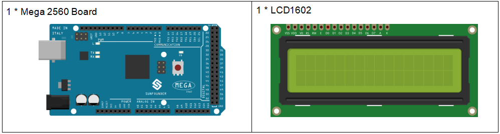
In this lesson, we will learn how to use an LCD1602 to display characters and strings. LCD1602, or 1602 character-type liquid crystal display, is a kind of dot matrix module to show letters, numbers, and characters and so on. It’s composed of 5×7 or 5×11 dot matrix positions; each position can display one character. There’s a dot pitch between two characters and a space between lines, thus separating characters and lines. The number 1602 means on the display, 2 rows can be showed and 16 characters in each. Now let’s check more details!
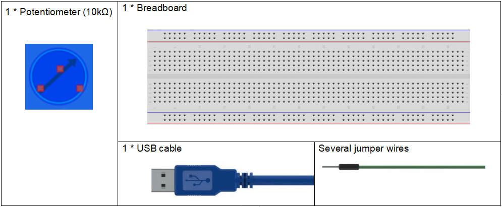
Components
Experimental Principle
Generally, LCD1602 has parallel ports, that is, it would control several pins at the same time. LCD1602 can be categorized into eight-port and four-port connections. If the eight-port connection is used, then all the digital ports of the Mega 2560 board are almost completely occupied. If you want to connect more sensors, there will be no ports available. Therefore, the four-port connection is used here for better application.
Pins of LCD1602 and their functions
VSS: connected to ground
VDD: connected to a +5V power supply
VO: to adjust the contrast
RS: A register select pin that controls where in the LCD’s memory you are writing data to. You can select either the data register, which holds what goes on the screen, or an instruction register, which is where the LCD’s controller looks for instructions on what to do next.
R/W: A Read/Write pin to select between reading and writing mode
E: An enabling pin that reads the information when High level (1) is received. The instructions are run when the signal changes from High level to Low level.
D0-D7: to read and write data
A and K: Pins that control the LCD backlight. Connect K to GND and A to 3.3v. Open the backlight and you will see clear characters in a comparatively dark environment.
Principle:
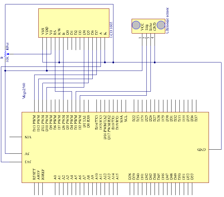
Connect K to GND and A to 3.3 V, and then the backlight of the LCD1602 will be turned on. Connect VSS to GND and the LCD1602 to the power source. Connect VO to the middle pin of the potentiometer – with it you can adjust the contrast of the screen display. Connect RS to D4 and R/W pin to GND, which means then you can write characters to the LCD1602. Connect E to pin6 and the characters displayed on the LCD1602 are controlled by D4-D7. For programming, it is optimized by calling function libraries.
The schematic diagram:
Experimental Procedures
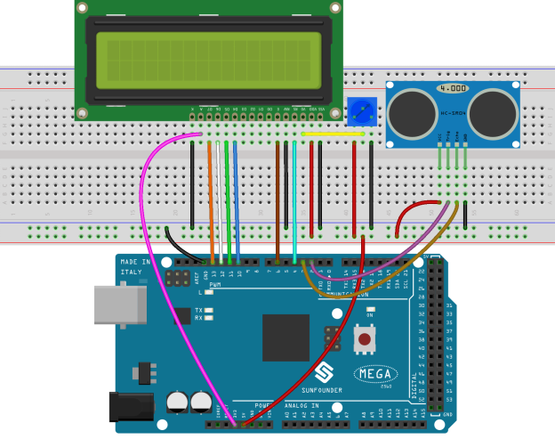
Step 1: Build the circuit
Step 2: Open the code file.
Step 3: Select the Board and Port.
Step 4: Upload the sketch to the board.
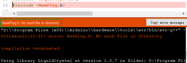
Note:If you receive the following error, it is because you didn’t add a library named NewPing, please refer to Lesson 2 Add libraries to add it.
Now, if you use a piece of paper to approach or keep it far away from the sensor. You will see the value displayed on the LCD changes, which indicates the distance between the paper and the ultrasonic sensor.

Code Analysis
Code Analysis 15-1 Initialize the ultrasonic sensor and LCD1602
#include <LiquidCrystal.h>                          // use #include  to define the header file.
#include <NewPing.h>                                // use #include  to define the header file.

LiquidCrystal lcd(4, 6, 10, 11, 12, 13);            //lcd(RS,E,D4,D5,D6,D7)

#define TRIGGER_PIN  2                              //  trig pin on the ultrasonic sensor attach to pin2 .
#define ECHO_PIN     3                              //  echo pin on the ultrasonic sensor attach to pin3.
#define MAX_DISTANCE 400                            // Maximum distance we want to ping for (in centimeters). Maximum sensor distance is rated at 400-500cm.

NewPing sonar(TRIGGER_PIN, ECHO_PIN, MAX_DISTANCE); // NewPing setup of pins and maximum distance.
Create a NewPing variable sonar. The basic format of NewPing is: NewPing (uint8_t trigger_pin, uint8_t echo_pin, int max_cm_distance). Here uint8 comes up again. As we mentioned previously in lesson 8 of the RFID series, uint means an unsigned integer and 8 means 8 bits. So a value in the uint8 format here means an unsigned-char type value.
Code Analysis 15-2 Convert the time to distance
unsigned int uS = sonar.ping(); // Send ping, get ping time in microseconds (uS).ping() here is to calculate the time from pulse sending to receiving. Define a vairal uS and assign the time to it. Its unit should be microsecond (us).
int distance = uS / US_ROUNDTRIP_CM;uS / US_ROUNDTRIP_CM is a formula to convert the time between ping sending and receiving into a distance. The unit is cm.
Code Analysis 15-3 Display the distance on the LCE1602
lcd.setCursor(0, 0);       //Place the cursor at Line 1, Column 1. From here the characters are to be displayed
lcd.print("Distance:");    //Print Distance: on the LCD
lcd.setCursor(0, 1);       //Set the cursor at Line 1, Column 0
lcd.print("             ");//Here is to leave some spaces after the characters so as to clear the previous characters that may still remain.
lcd.setCursor(9, 1);       //Set the cursor at Line 1, Column 9.
lcd.print(distance);       // print on the LCD the value of the distance converted from the time between ping sending and receiving.
lcd.setCursor(12, 1);      //Set the cursor at Line 1, Column 12.
lcd.print("cm");           //print the unit "cm"