Introduction
If you ask anyone in the know to rank the most commonly and widely used IC, the famous 555 time base IC would certainly be at the top of the list. The 555 – a mixed circuit composed of analog and digital circuits – integrates analogue and logical functions into an independent IC, and hence tremendously expands the application range of analog integrated circuits. The 555 is widely used in various timers, pulse generators, and oscillators. In this experiment, the SunFounder Uno board is used to test the frequencies of square waves generated by the 555 oscillating circuit and show them on Serial Monitor.
Components
– 1 * SunFounder Uno board
– 1 * USB cable
– Jumper wires
– 1 * Breadboard
– 1 * NE555
– 2 * 104 ceramic capacitor
– 1 * Potentiometer (50KΩ)
– 1 * Resistor (10KΩ)
Principle
The 555 IC was originally used as a timer, hence the name 555 time base circuit. It is now widely used in various electronic products because of its reliability, convenience, and low price. The 555 is a complex hybrid circuit with dozens of components such as a divider, comparator, basic R-S trigger, discharge tube, and buffer.
555 chip pins are introduced as follows:
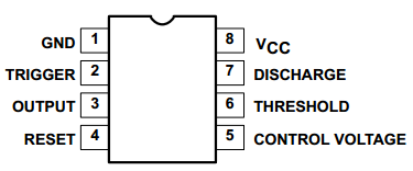
As shown in the picture, the 555 ICis dual in-line with the 8-pin package. Thus:
- Pin 1 (GND): the ground;
- Pin 2 (TRIGGER ): the input of lower comparator;
- Pin 3 (OUTPUT): having two states of 0 and 1 decided by the input electrical level;
- Pin 4 (RESET): output low level when supplied a low one;
- Pin 5 (CONTROL VOLTAGE): changing the upper and lower level trigger values;
- Pin 6 (THRESHOLD): the input of upper comparator;
- Pin 7 (DISCHARGE): having two states of suspension and ground connection also decided by input, and the output of the internal discharge tube;
- Pin 8 (VCC): the power supply;
Experimental Procedures
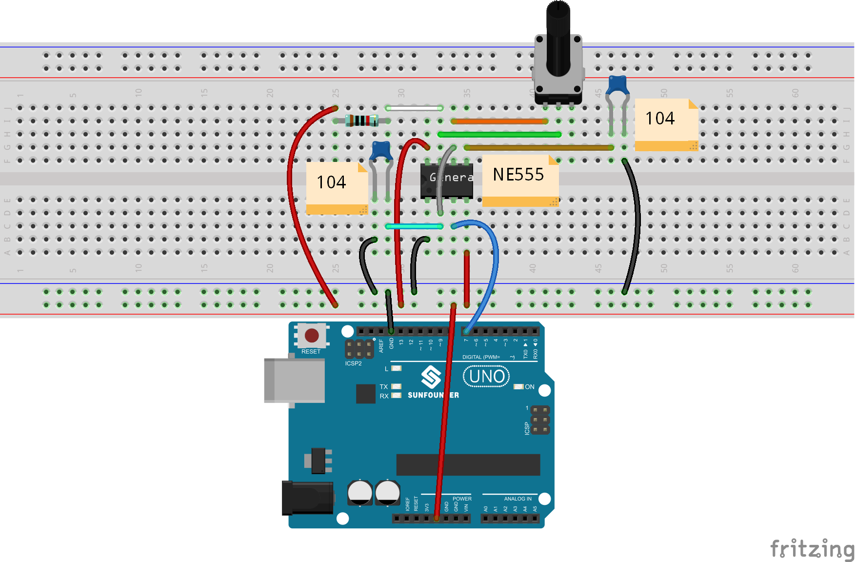
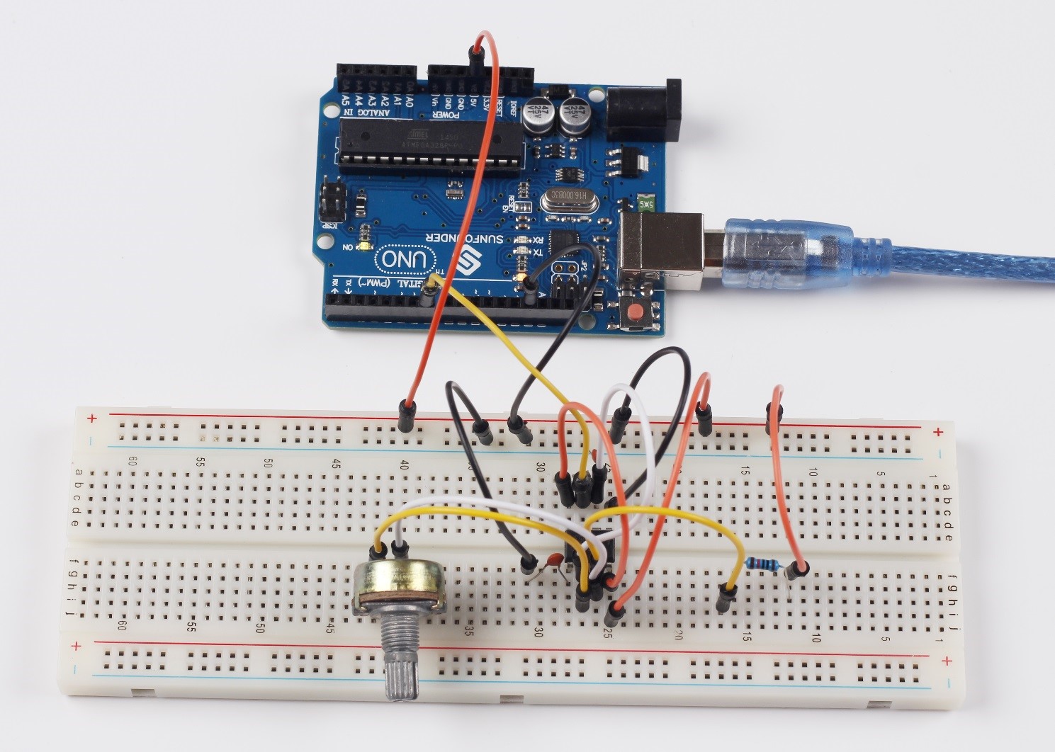
Step 1: Build the circuit
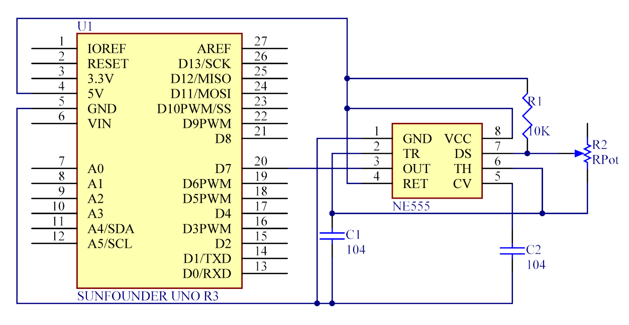
The schematic diagram
Step 2: Program (please go to our official website www.sunfounder.com to download related code by clicking LEARN -> Get Tutorials)
Step 3: Compile the code
Step 4: Upload the sketch to the SunFounder Uno board
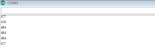
After uploading, open the serial monitor and you will see the following page.
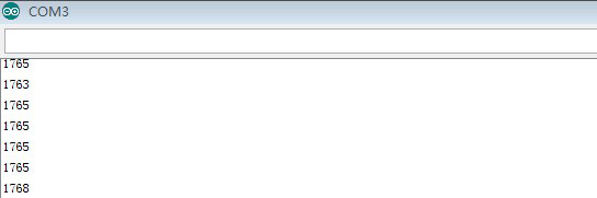
If you adjust the potentiometer, the length of the pulse (in microsecond) displayed will change accordingly.
Code
| //NE555 Timer//After burning the program, open the serial monitor,you can see that if you rotate the potentiometer, the length of the pulse (in microsecond) displayed will change accordingly. //Email:support@sunfounder.com //Website:www.sunfounder.com //2015.5.7 int pin = 7; //pin 7 connected to the third pin of NE555 unsigned long duration; //the variable to store the length of the pulse void setup() { pinMode(pin, INPUT); //set the pin as an input Serial.begin(9600); // start serial port at 9600 bps } void loop() { duration = pulseIn(pin, HIGH); //Reads a pulse on pin Serial.print(duration); //print the length of the pulse on the serial monitor Serial.println(); //print an blank on serial monitor delay(500); //wait for 500 ms } |
Video