Introduction
A photo-interrupter is a sensor that arranges light-emitting component and light-receiving component face-to-face and packages them together. It applies the principle that light is interrupted when an object passes through the sensor. Therefore, photo-interrupters are widely used in speed measurement.
Components
– 1 * Raspberry Pi
– 1 * Breadboard
– 1 * Network cable (or USB wireless network adapter)
– 1 * Dual-color Common-Cathode LED module
– 1 * Photo-interrupter module
– Several jumper wires
Experimental Principle
Basically a photo-interrupter consists of two parts: transmitter and receiver. The transmitter (e.g., an LED or a laser) emits light and then the light goes to the receiver. If that light beam between the transmitter and receiver is interrupted by an obstacle, the receiver will detect no incoming light even for a moment and the output level will change. In this experiment, we will turn an LED on or off by using this change.
Experimental Procedures
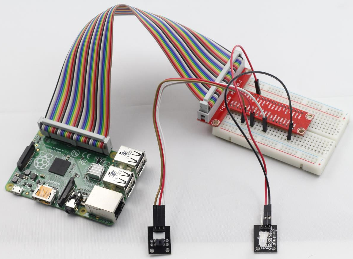
Step 1: Build the circuit
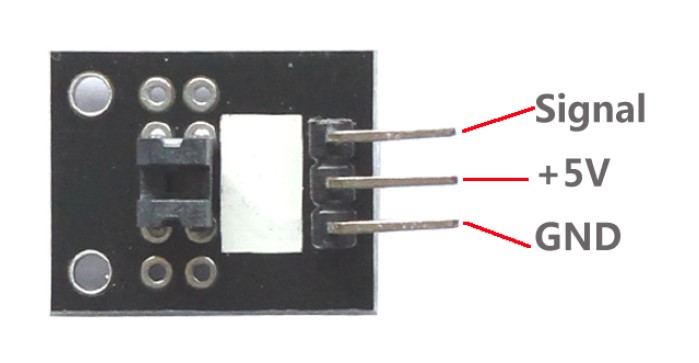
Photo-interrupter Raspberry Pi
S ———————————– GPIO0
+ ———————————- 3.3V
– ———————————- GND
Dual-color LED module connection: connect pin R on dual-color LED module to GPIO1 of the Raspberry Pi; GND to GND
Step 2: Edit and save the code (see path/Rpi_SensorKit_code/14_lightBreak/lightBreak.c)
Step 3: Compile
gcc lightBreak.c -lwiringPi
Step 4: Run
./a.out
Block incident light with a piece of paper. The LED will light up and a string “led on” will be printed on the screen. Remove the paper and the LED will be off and a string “led off” will be printed on the screen.
lightBreak.c
#include <wiringPi.h>
#include <stdio.h>

#define LightBreakPin     0
#define LedPin            1

int main(void)
{
	if(wiringPiSetup() == -1){ //when initialize wiring failed,print messageto screen
		printf("setup wiringPi failed !");
		return 1;
	}
//	printf("linker LedPin : GPIO %d(wiringPi pin)\n",VoicePin); //when initialize wiring successfully,print message to screen

	pinMode(LightBreakPin, INPUT);
	pinMode(LedPin,  OUTPUT);

	while(1){
		if(digitalRead(LightBreakPin) == HIGH){
			printf("led on !\n");
			digitalWrite(LedPin, HIGH);     //led on
		}
		else{
			printf("led off !\n");
			digitalWrite(LedPin, LOW);
		}
	}

	return 0;
}
Python Code
#!/usr/bin/env python
import RPi.GPIO as GPIO

LightBreakPin = 11
LedPin = 12

def setup():
	GPIO.setmode(GPIO.BOARD)       # Numbers GPIOs by physical location
	GPIO.setup(LedPin, GPIO.OUT)   # Set LedPin's mode is output
	GPIO.setup(LightBreakPin, GPIO.IN, pull_up_down=GPIO.PUD_UP)
	GPIO.output(LedPin, GPIO.LOW) # Set LedPin low to off led

def swLed(channel):
	status = GPIO.input(LightBreakPin)
	print "LED: on" if status else "LED: off"
	GPIO.output(LedPin,status)

def loop():
	GPIO.add_event_detect(LightBreakPin, GPIO.BOTH, callback=swLed) # wait for falling
	while True:
		pass
def destroy():
	GPIO.output(LedPin, GPIO.LOW)     # led off
	GPIO.cleanup()                     # Release resource

if __name__ == '__main__':     # Program start from here
	setup()
	try:
		loop()
	except KeyboardInterrupt:  # When 'Ctrl+C' is pressed, the child program destroy() will be  executed.
		destroy()