Introduction
Since we’ve got some knowledge of the 74HC595 in the previous lesson, now let’s try to use it and drive a 7-segment display to show a figure from 0 to 9 and A to F.
Components
– 1 * Raspberry Pi
– 1 * Breadboard
– 1 * 74HC595
– 1 * 7-segment display
– 1 * Resistor (220Ω)
– Jumper wires
Principle
7-Segment Display
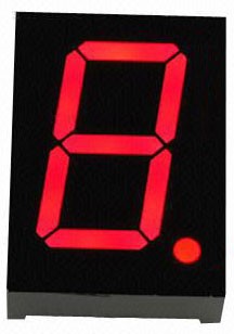
A 7-segment display is an 8-shaped component which packages 7 LEDs. Each LED is called a segment – when energized, one segment forms part of a numeral (both decimal and hexadecimal) to be displayed. An additional 8th LED is sometimes used within the same package thus allowing the indication of a decimal point (DP) when two or more 7-segment displays are connected together to display numbers greater than ten.
Each of the LEDs in the display is given a positional segment with one of its connection pins led out from the rectangular plastic package. These LED pins are labeled from “a” through to “g” representing each individual LED. The other LED pins are connected together forming a common pin. So by forward biasing the appropriate pins of the LED segments in a particular order, some segments will brighten and others stay dim, thus showing the corresponding character on the display.
The common pin of the display generally tells its type. There are two types of pin connection: a pin of connected cathodes and one of connected anodes, indicating Common Cathode (CC) and Common Anode (CA). As the name suggests, a CC display has all the cathodes of the 7 LEDs connected when a CA display has all the anodes of the 7 segments connected.
Common Cathode 7-Segment Display
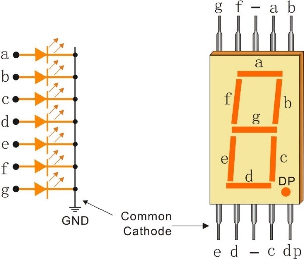
In a common cathode display, the cathodes of all the LED segments are connected to the logic “0” or ground. Then an individual segment (a-g) is energized by a “HIGH”, or logic “1” signal via a current limiting resistor to forward bias the anode of the segment.
Common Anode 7-Segment Display
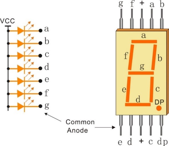
In a common anode display, the anodes of all the LED segments are connected to the logic “1”. Then an individual segment (a-g) is energized by a ground, logic “0” or “LOW” signal via a current limiting resistor to the cathode of the segment.
In this experiment, a common cathode 7-segment display is use. It should be connected to ground. When the anode of an LED in a certain segment is at high level, the corresponding segment will light up; when it is at low, the segment will stay dim.
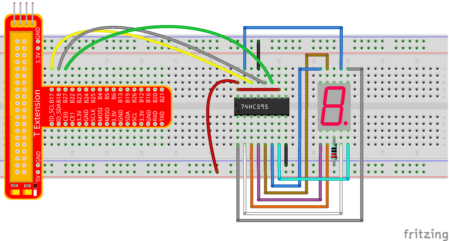
The schematic diagram is shown as below:
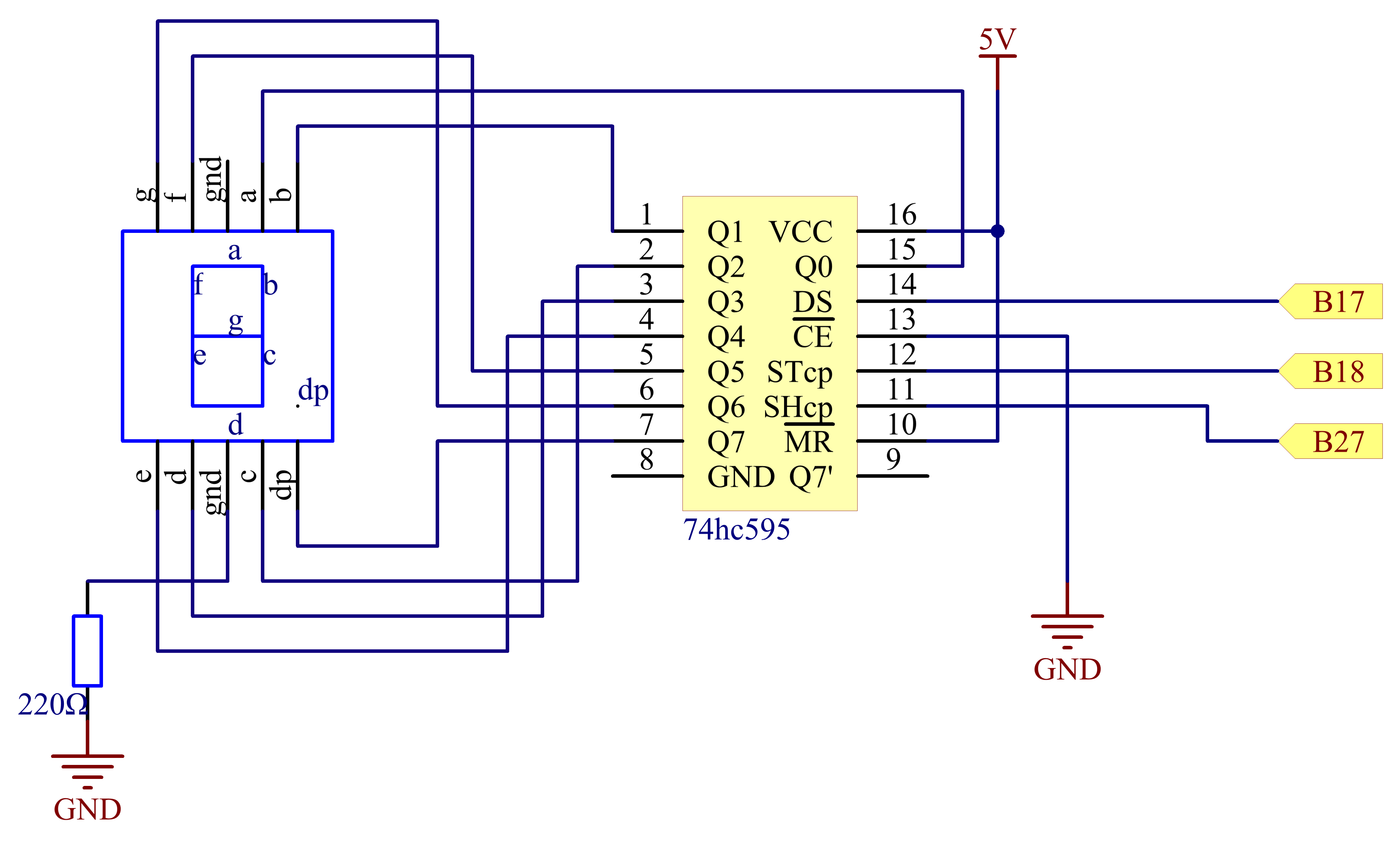
Principle: Connect pin ST_CP of 74HC595 to Raspberry Pi B18, SH_CP to B27, DS to B17, parallel output ports to 8 segments of the LED segment display. Input data in DS pin to shift register when SH_CP (the clock input of the shift register) is at the rising edge, and to the memory register when ST_CP (the clock input of the memory) is at the rising edge. Then you can control the states of SH_CP and ST_CP via the Raspberry Pi GPIOs to transform serial data input into parallel data output so as to save Raspberry Pi GPIOs and drive the display.
Experimental Procedures
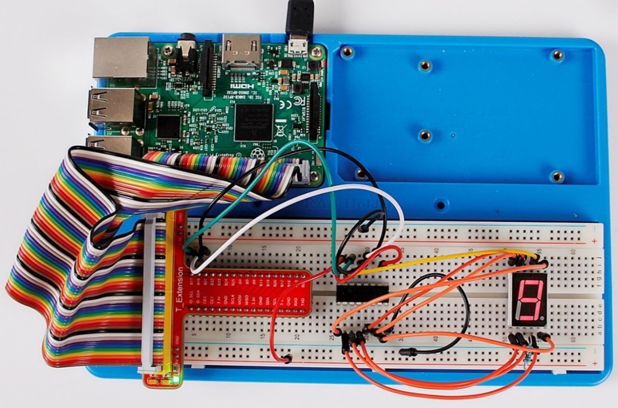
Step 1: Build the circuit
For C language users:
Step 2: Get into the folder of the code.
cd /home/pi/SunFounder_Super_Kit_V3.0_for_Raspberry_Pi/C
Step 3: Compile
make 14_segment
Step 4: Run the executable file above.
sudo ./14_segment
For Python users:
Step 2: Get into the folder of the code.
cd /home/pi/SunFounder_Super_Kit_V3.0_for_Raspberry_Pi/Python
Step 3: Run
sudo python 14_segment.py
If you want to display a number, use the hc595_shift() function, segCode list and decimal value x in the sketch:
hc595_shift(segCode[x]) # x is a number needs to be displayed ranging from 0~15, and it will be coverted and displayed by 0~F in hexadecimal.
Note: The hexadecimal format of number 0~15 are (0, 1, 2, 3, 4, 5, 6, 7, 8, 9, A, B, C, D, E, F).
You should see the 7-segment display from 0 to 9 and A to F.
Further Exploration
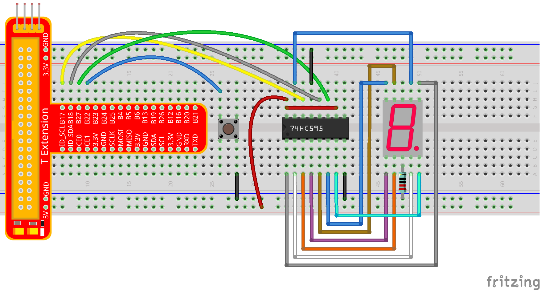
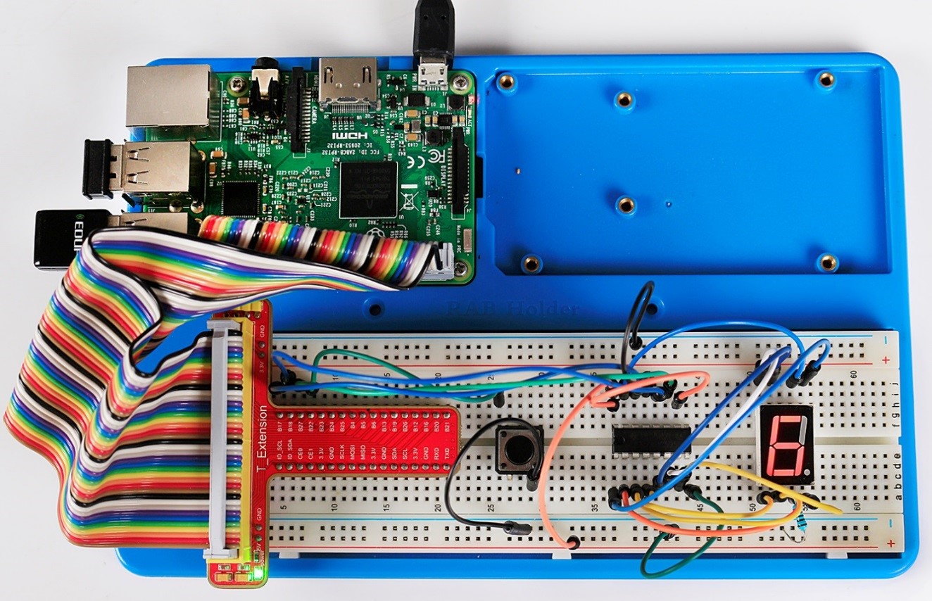
You can slightly modify the hardware and software based on this experiment to make a dice. For hardware, add a button to the original board.
Build the circuit:
Get into the folder of the code.
cd /home/pi/SunFounder_Super_Kit_V3.0_for_Raspberry_Pi/C
Next, Compile the Code
make 14_dice
Run
sudo ./14_dice
For Python users:
Step 2: Get into the folder of the code.
cd /home/pi/SunFounder_Super_Kit_V3.0_for_Raspberry_Pi/Python
Step 3: Run
sudo python 14_dice.py
Now you should see a number flashing between 0 and 6 quickly on the segment display. Press the button on the breadboard, and the display will statically display a random number between 0 and 6 for 2 seconds and then circularly flash randomly between 0 and 6 again.
Summary
Through this lesson, you may have mastered the basic principle and programming for 7-segment display based on Raspberry Pi, as well as more knowledge about using 74HC595. Now you can apply what you’ve learnt and put it into practice to create your own works!
C Code
/**********************************************************************
* Filename    : segment.c
* Description : Use 74HC595 to control segment.
* Author      : Robot
* E-mail      : support@sunfounder.com
* website     : www.sunfounder.com
* Update      : Cavon    2016/07/01
**********************************************************************/
#include <wiringPi.h>
#include <stdio.h>

#define   SDI   0   //serial data input
#define   RCLK  1   //memory clock input(STCP)
#define   SRCLK 2   //shift register clock input(SHCP)

unsigned char SegCode[17] = {0x3f,0x06,0x5b,0x4f,0x66,0x6d,0x7d,0x07,0x7f,0x6f,0x77,0x7c,0x39,0x5e,0x79,0x71,0x80};

void init(void){
	pinMode(SDI, OUTPUT); //make P0 output
	pinMode(RCLK, OUTPUT); //make P0 output
	pinMode(SRCLK, OUTPUT); //make P0 output

	digitalWrite(SDI, 0);
	digitalWrite(RCLK, 0);
	digitalWrite(SRCLK, 0);
}

void hc595_shift(unsigned char dat){
	int i;

	for(i=0;i<8;i++){
		digitalWrite(SDI, 0x80 & (dat << i));
		digitalWrite(SRCLK, 1);
		delay(1);
		digitalWrite(SRCLK, 0);
	}

		digitalWrite(RCLK, 1);
		delay(1);
		digitalWrite(RCLK, 0);
}

int main(void){
	int i;

	if(wiringPiSetup() == -1){ //when initialize wiring failed, print messageto screen
		printf("setup wiringPi failed !");
		return 1;
	}

	init();

	printf("\n");
	printf("\n");
	printf("========================================\n");
	printf("|         Segment with 74HC595         |\n");
	printf("|    ------------------------------    |\n");
	printf("|         SDI connect to GPIO0         |\n");
	printf("|         RCLK connect to GPIO1        |\n");
	printf("|        SRCLK connect to GPIO 2       |\n");
	printf("|                                      |\n");
	printf("|     Control segment with 74HC595     |\n");
	printf("|                                      |\n");
	printf("|                            SunFounder|\n");
	printf("========================================\n");
	printf("\n");
	printf("\n");

	while(1){
		for(i=0;i
Python Code
#!/usr/bin/env python

import RPi.GPIO as GPIO
import time

# Set up pins
SDI   = 17
RCLK  = 18
SRCLK = 27

# Define a segment code from 0 to F in Hexadecimal
# Commen cathode
segCode = [0x3f,0x06,0x5b,0x4f,0x66,0x6d,0x7d,0x07,0x7f,0x6f,0x77,0x7c,0x39,0x5e,0x79,0x71]
# Commen anode
# segCode = [0xc0,0xf9,0xa4,0xb0,0x99,0x92,0x82,0xf8,0x80,0x90,0x88,0x83,0xc6,0xa1,0x86,0x8e]

def print_msg():
	print ("========================================")
	print ("|         Segment with 74HC595         |")
	print ("|    ------------------------------    |")
	print ("|         SDI connect to GPIO0         |")
	print ("|         RCLK connect to GPIO1        |")
	print ("|        SRCLK connect to GPIO 2       |")
	print ("|                                      |")
	print ("|     Control segment with 74HC595     |")
	print ("|                                      |")
	print ("|                            SunFounder|")
	print ("========================================\n")
	print 'Program is running...'
	print 'Please press Ctrl+C to end the program...'
	raw_input ("Press Enter to begin\n")

def setup():
	GPIO.setmode(GPIO.BCM)
	GPIO.setup(SDI, GPIO.OUT, initial=GPIO.LOW)
	GPIO.setup(RCLK, GPIO.OUT, initial=GPIO.LOW)
	GPIO.setup(SRCLK, GPIO.OUT, initial=GPIO.LOW)

# Shift the data to 74HC595
def hc595_shift(dat):
	for bit in range(0, 8):
		GPIO.output(SDI, 0x80 & (dat << bit))
		GPIO.output(SRCLK, GPIO.HIGH)
		time.sleep(0.001)
		GPIO.output(SRCLK, GPIO.LOW)
	GPIO.output(RCLK, GPIO.HIGH)
	time.sleep(0.001)
	GPIO.output(RCLK, GPIO.LOW)

def main():
	print_msg()
	while True:
		# Shift the code one by one from segCode list
		for code in segCode:
			hc595_shift(code)
			print "segCode[%s]: 0x%02X"%(segCode.index(code), code) # double digit to print
			time.sleep(0.5)

def destroy():
	GPIO.cleanup()

if __name__ == '__main__':
	setup()
	try:
		main()
	except KeyboardInterrupt:
		destroy()