Introduction
The ADXL335 is a small, thin, low power, complete 3-axis accelerometer with signal-conditioned voltage outputs. It measures acceleration with a minimum full-scale range of ±3g. It can measure the static acceleration of gravity in tilt-sensing applications, as well as dynamic acceleration resulting from motion, shock, or vibration.
Components
– 1 * SunFounder Uno board
– 1 * Breadboard
– 1 * ADXL335 module
– 1 * USB cable
– Jumper wires
Principle
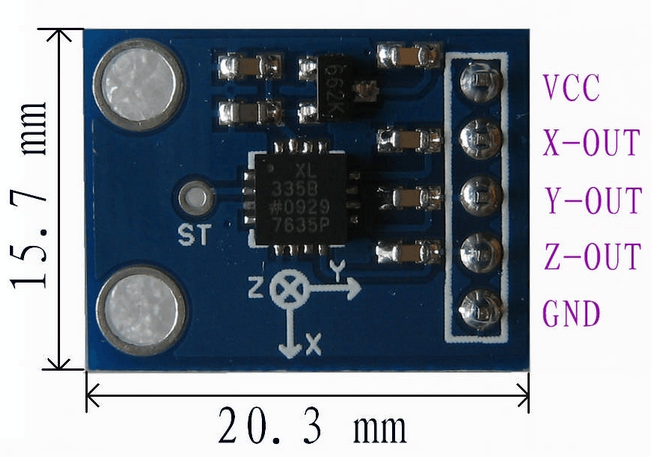
ADXL335
The ADXL335 uses a 5*5*2 mm LCC packaging when the ambient temperature ranges from -55℃ to125℃. It is exceptionally light, and the size of the PCB module is only16mm*20mm, as shown in the following picture. It’s quite convenient for embedding hardware for engineering projects. The operating voltage of ADXL335 ranges from 1.8V to 3.6V. it can obtain power from analog port A0 and A4 of the SunFounder Uno board. However, for convenience, we directly supply 3.3V voltage from the SunFounder Uno board to the ADXL335. Do not use the 5V voltage of the SunFounder Uno board to supply power to the ADXL335.
What the ADXL335 outputs are analog voltage values; therefore, what you need to do is collect output voltage values when programming. Of course you also need to perform some engineering projects. If you want to test accurate figures, you need to edit more code according to relevant data manuals.
Experimental Procedures
Step 1: Build the circuit
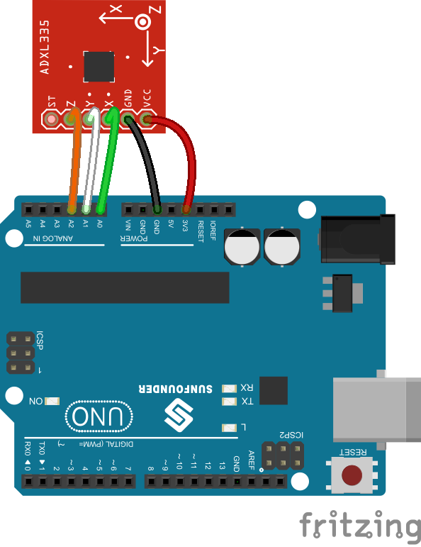
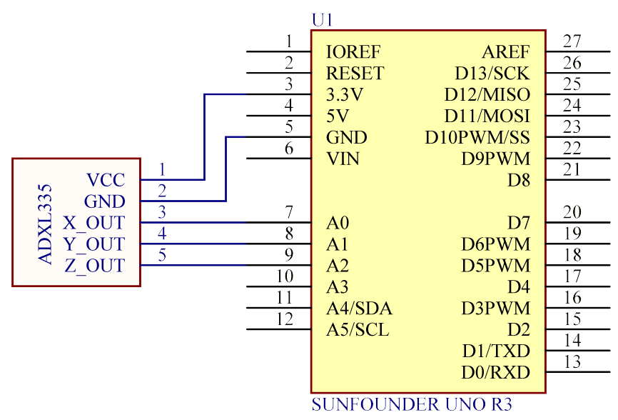
The schematic diagram
Step 2: Program (please go to our official website www.sunfounder.com to download related code by clicking LEARN -> Get Tutorials)
Step 3: Debug the code
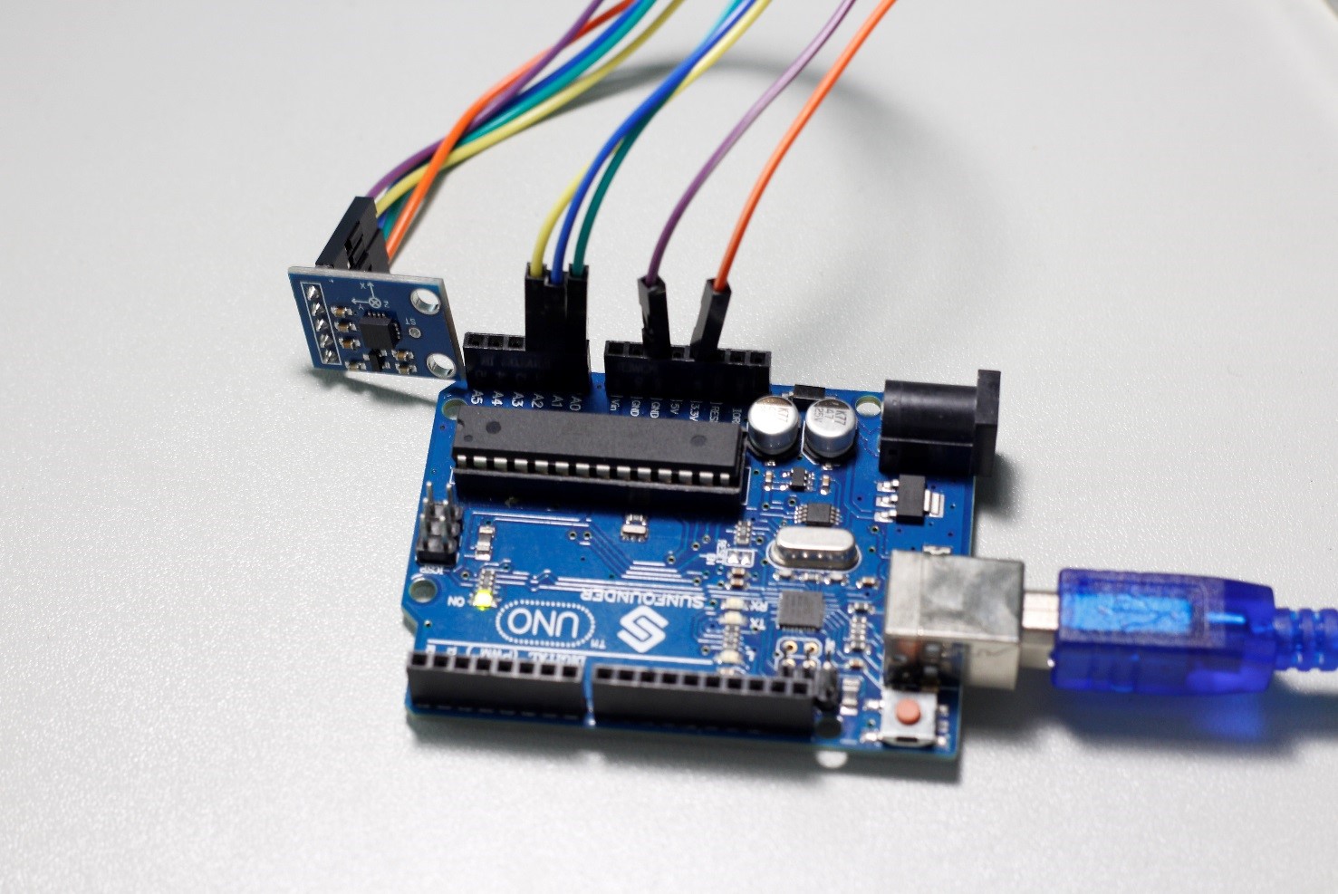
Step 4: Upload the sketch to the SunFounder Uno board
After uploading, open Serial Monitor, where you can see the data detected. When the acceleration of the module changes, the figure will change accordingly.
Code
| //ADXL335 /******************************** ADXL335 note:vcc–>5v ,but ADXL335 Vs is 3.3V The circuit: 5V: VCC analog 0: x-axis analog 1: y-axis analog 2: z-axis After burning the program, open the serial monitor debugging window, where you can see the data detected being displayed. When the acceleration varies, the figure will vary accordingly. *********************************/ //Email:support@sunfounder.com //Website:www.sunfounder.com //2015.5.7 const int xpin = A0; // x-axis of the accelerometer const int ypin = A1; // y-axis const int zpin = A2; // z-axis (only on 3-axis models) void setup() { // initialize the serial communications: Serial.begin(9600); } void loop() { int x = analogRead(xpin); //read from xpin delay(1); // int y = analogRead(ypin); //read from ypin delay(1); int z = analogRead(zpin); //read from zpin float zero_G = 512.0; //ADC is 0~1023 the zero g output equal to Vs/2 //ADXL335 power supply by Vs 3.3V float scale = 102.3; //ADXL335330 Sensitivity is 330mv/g //330 * 1024/3.3/1000 /*Serial.print(x); Serial.print(“\t”); Serial.print(y); Serial.print(“\t”); Serial.print(z); Serial.print(“\n”);*/ Serial.print(((float)x – 331.5)/65*9.8); //print x value on serial monitor Serial.print(“\t”); Serial.print(((float)y – 329.5)/68.5*9.8); //print y value on serial monitor Serial.print(“\t”); Serial.print(((float)z – 340)/68*9.8); //print z value on serial monitor Serial.print(“\n”); delay(1000); //wait for 1 second } |
Video