Introduction
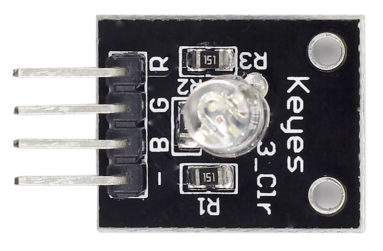
RGB LED modules can emit various colors of light. Three LEDs of red, green, and blue are packaged into a transparent or semitransparent plastic shell with four pins led out. The three primary colors of red, green, and blue can be mixed and compose all kinds of colors by brightness, so you can make an RGB LED emit colorful light by controlling the circuit.
Components
– 1* SunFounder Uno board (or SunFounder Mega2560 board)
– 1*USB data cable
– 1*RGB LED module
– Several jumper wires
Experimental Principle
In this experiment, we will use PWM technology to control the brightness of RGB. We’ve described the concept in Lesson 2 of this kit. You may check the information, if necessary.
Each of the three color channels: red, green, and blue, has 255 stages of brightness. When the three primary colors are all 0, the LED light is turned off. When the colors are all 255, the LED gets brightest. Here we input any value between 0 and 255 to the three pins of the RGB LED to make it display different colors.
RGB LEDs can be categorized into common anode type and common cathode type. In this experiment, we use common cathode RGB LED.
Experimental Procedures
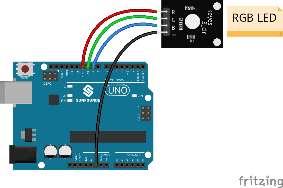
Step 1: Build the circuit
| RGB LED module | SunFounder Uno |
| R | 11 |
| G | 10 |
| B | 9 |
| – | GND |
Step 2: Program (Please refer to the example code in LEARN -> Get Tutorials on our website)
Step 3: Compile the code
Step 4: Upload the sketch to the SunFounder Uno board
Now, you can see the RGB LED flash red, green and blue first, and then change to red, orange, yellow, green, blue, indigo and purple.

Code
| /*************************************************************************/ const int redPin = 11; // R petal on RGB LED module connected to digital pin 11 const int greenPin = 10; // G petal on RGB LED module connected to digital pin 9 const int bluePin = 9; // B petal on RGB LED module connected to digital pin 10 /**************************************************************************/ void setup() { pinMode(redPin, OUTPUT); // sets the redPin to be an output pinMode(greenPin, OUTPUT); // sets the greenPin to be an output pinMode(bluePin, OUTPUT); // sets the bluePin to be an output } /***************************************************************************/ void loop() // run over and over again { // Basic colors: color(255, 0, 0); // turn the RGB LED red delay(1000); // delay for 1 second color(0,255, 0); // turn the RGB LED green delay(1000); // delay for 1 second color(0, 0, 255); // turn the RGB LED blue delay(1000); // delay for 1 second // Example blended colors: color(255,0,0); // turn the RGB LED red delay(1000); // delay for 1 second color(237,109,0); // turn the RGB LED orange delay(1000); // delay for 1 second color(255,215,0); // turn the RGB LED yellow delay(1000); // delay for 1 second color(0,255,0); // turn the RGB LED green delay(1000); // delay for 1 second color(0,0,255); // turn the RGB LED blue delay(1000); // delay for 1 second color(0,46,90); // turn the RGB LED indigo delay(1000); // delay for 1 second color(128,0,128); // turn the RGB LED purple delay(1000); // delay for 1 second } /******************************************************/ void color (unsigned char red, unsigned char green, unsigned char blue) // the color generating function { analogWrite(redPin, red); analogWrite(bluePin, blue); analogWrite(greenPin, green); } /******************************************************/ |