Introduction
Based on Hall Effect, a Hall sensor is a one that varies its output voltage in response to a magnetic field. Hall sensors are used for proximity switching, positioning, speed detection, and current sensing applications.
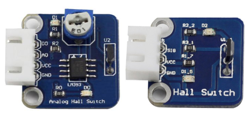
Hall sensors can be categorized into linear (analog) Hall sensors and switch Hall sensors. A switch Hall sensor consists of voltage regulator, Hall element, differential amplifier, Schmitt trigger, and output terminal and it outputs digital values. A linear Hall sensor consists of Hall element, linear amplifier, and emitter follower and it outputs analog values. If you add a comparator to a linear (analog) Hall sensor it will be able to output both analog and digital signals.
Components
– 1 * Raspberry Pi
– 1 * Breadboard
– 1 * Network cable (or USB wireless network adapter)
– 1 * Analog Hall Switch module
– 1 * Dual-color LED module
– 1 * Switch hall module
– 1 * PCF8591
– 2 * 3-Pin anti-reverse cable
– 1 * 4-Pin anti-reverse cable
– Several Jumper wires (M to F)
Experimental Principles
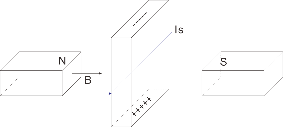
Hall Effect
Hall Effect is a kind of electromagnetic effect. It was discovered by Edwin Hall in 1879 when he was researching conductive mechanism about metals. The effect is seen when a conductor is passed through a uniform magnetic field. The natural electron drift of the charge carriers causes the magnetic field to apply a Lorentz force (the force exerted on a charged particle in an electromagnetic field) to these charge carriers. The result is what is seen as a charge separation, with a buildup of either positive or negative charges on the bottom or on the top of the plate.
Hall Sensor
A Hall sensor is a kind of magnetic field sensor based on it.
Electricity carried through a conductor will produce a magnetic field that varies with current, and a Hall sensor can be used to measure the current without interrupting the circuit. Typically, the sensor is integrated with a wound core or permanent magnet that surrounds the conductor to be measured.
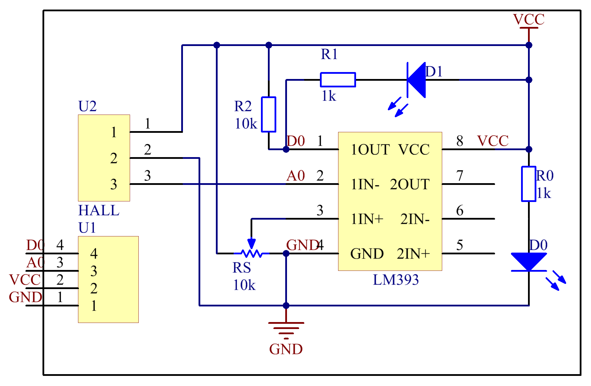
The schematic diagram of the analog Hall sensor module:
The schematic diagram of the Switch hall module:
Experimental Procedures
For switch Hall sensor, take the following steps.
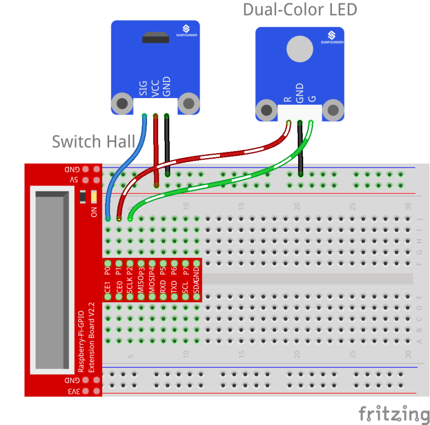
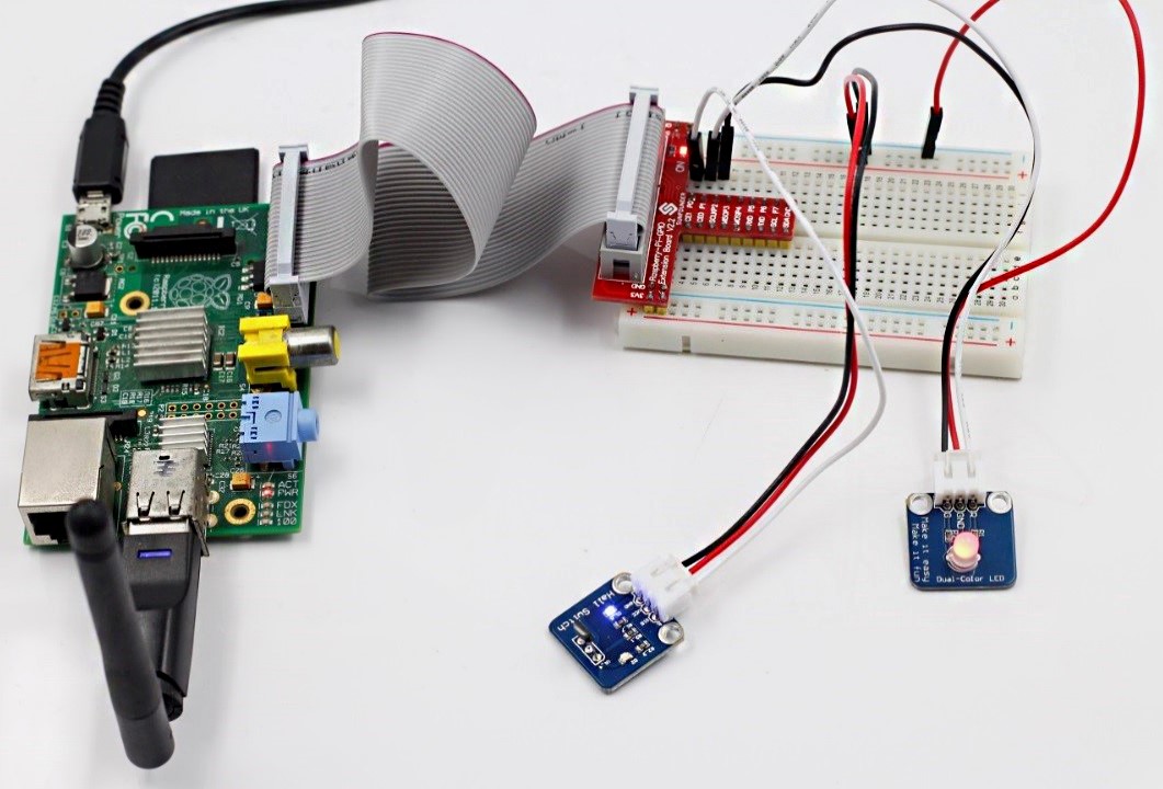
Step 1: Build the circuit
| Raspberry Pi | Switch Hall Module | Raspberry Pi | Dual-color LED Module | |
| GPIO0 | SIG | GPIO1 | R | |
| 5V | VCC | GND | GND | |
| GND | GND | GPIO2 | G |
For C language users:
Step 2: Change directory
cd /home/pi/SunFounder_SensorKit_for_RPi2/C/17_switch_hall/
Step 3: Compile
gcc switch_hall.c –lwiringPi
Step 4: Run
sudo ./a.out
For Python users:
Step 2: Change directory
cd /home/pi/SunFounder_SensorKit_for_RPi2/Python/
Step 3: Run
sudo python 17_switch_Hall.py
Put a magnet close to the Switch Hall sensor. Then a string “Detected magnetic materials” will be printed on the screen and the LED will light up.
For Analog Hall Switch, take the following steps
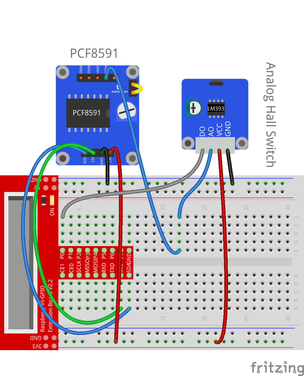
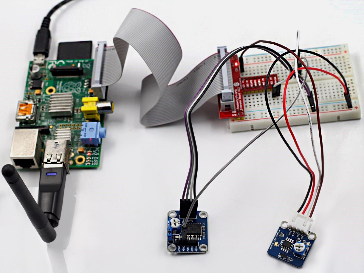
Step 1: Build the circuit
| Raspberry Pi | PCF8591 Module | Analog Hall Switch |
| SDA | SDA | * |
| SCL | SCL | * |
| 3V3 | VCC | VCC |
| GND | GND | GND |
| GPIO0 | * | DO |
| * | AIN0 | AO |
For C language users:
Step 2: Change directory
cd /home/pi/SunFounder_SensorKit_for_RPi2/C/17_analog_hall_switch/
Step 3: Compile
gcc analog_hall_switch.c –lwiringPi
Step 4: Run
sudo ./a.out
For Python users:
Step 2: Change directory
cd /home/pi/SunFounder_SensorKit_for_RPi2/Python/
Step 3: Run
sudo python 17_analog_hall_switch.py
Now “Current intensity of magnetic field : xxx ” will be displayed on the screen. Put the magnet close to the analog Hall sensor, with the north magnetic pole towards the sensor, and then ” Magnet: North.” will be displayed. Move the magnet away, and ” Magnet: None.” will be printed. If the magnet approaches the sensor with the south magnetic pole towards it, ” Magnet: South.” will be printed on the screen.
Note: Pin D0 of the Analog Hall Sensor will output “0” only when the south pole of the magnet approaches it, otherwise it will output “1”.
C Code
Analog Hall
#include <stdio.h>
#include <wiringPi.h>
#include <pcf8591.h>

#define PCF       120

int main (void)
{
	int res, tmp, status;
	wiringPiSetup ();
	// Setup pcf8591 on base pin 120, and address 0x48
	pcf8591Setup (PCF, 0x48);
	status = 0;
	while(1) // loop forever
	{
		res = analogRead(PCF + 0);
		printf("Current intensity of magnetic field : %d\n", res);
		if (res - 133 < 5 || res - 133 > -5)
			tmp = 0;
		if (res < 128) tmp = -1;
		if (res > 138) tmp =  1;
		if (tmp != status)
		{
			switch(tmp)
			{
				case 0:
					printf("\n*****************\n"  );
					printf(  "* Magnet: None. *\n"  );
					printf(  "*****************\n\n");
					break;
				case -1:
					printf("\n******************\n"  );
					printf(  "* Magnet: North. *\n"  );
					printf(  "******************\n\n");
					break;
				case 1:
					printf("\n******************\n"  );
					printf(  "* Magnet: South. *\n"  );
					printf(  "******************\n\n");
					break;
			}
			status = tmp;
		}
		delay (200);
	}
	return 0 ;
}
Switch Hall
#include <wiringPi.h>
#include <stdio.h>

#define HallPin		0
#define Gpin		1
#define Rpin		2

void LED(char* color)
{
	pinMode(Gpin, OUTPUT);
	pinMode(Rpin, OUTPUT);
	if (color == "RED")
	{
		digitalWrite(Rpin, HIGH);
		digitalWrite(Gpin, LOW);
	}
	else if (color == "GREEN")
	{
		digitalWrite(Rpin, LOW);
		digitalWrite(Gpin, HIGH);
	}
	else
		printf("LED Error");
}

int main(void)
{
	if(wiringPiSetup() == -1){ //when initialize wiring failed,print messageto screen
		printf("setup wiringPi failed !");
		return 1;
	}

	pinMode(HallPin, INPUT);
	LED("GREEN");

	while(1){
		if(0 == digitalRead(HallPin)){
			delay(10);
			if(0 == digitalRead(HallPin)){
				LED("RED");
				printf("Button is pressed\n");
			}
		}
		else if(1 == digitalRead(HallPin)){
			delay(10);
			if(1 == digitalRead(HallPin)){
				while(!digitalRead(HallPin));
				LED("GREEN");
			}
		}
	}
	return 0;
}
Python Code
Analog Hall
#/usr/bin/env python
import RPi.GPIO as GPIO
import PCF8591 as ADC
import time

def setup():
	ADC.setup(0x48)

def Print(x):
	if x == 0:
		print ''
		print '*************'
		print '* No Magnet *'
		print '*************'
		print ''
	if x == 1:
		print ''
		print '****************'
		print '* Magnet North *'
		print '****************'
		print ''
	if x == -1:
		print ''
		print '****************'
		print '* Magnet South *'
		print '****************'
		print ''

def loop():
	status = 0
	while True:
		res = ADC.read(0)
		print 'Current intensity of magnetic field : ', res
		if res - 133 < 5 and res - 133 > -5:
			tmp = 0
		if res < 128:
			tmp = -1
		if res > 138:
			tmp = 1
		if tmp != status:
			Print(tmp)
			status = tmp
		time.sleep(0.2)

if __name__ == '__main__':
	setup()
	loop()
Switch Hall
#!/usr/bin/env python
import RPi.GPIO as GPIO

HallPin = 11
Gpin   = 12
Rpin   = 13

def setup():
	GPIO.setmode(GPIO.BOARD)       # Numbers GPIOs by physical location
	GPIO.setup(Gpin, GPIO.OUT)     # Set Green Led Pin mode to output
	GPIO.setup(Rpin, GPIO.OUT)     # Set Red Led Pin mode to output
	GPIO.setup(HallPin, GPIO.IN, pull_up_down=GPIO.PUD_UP)    # Set BtnPin's mode is input, and pull up to high level(3.3V)
	GPIO.add_event_detect(HallPin, GPIO.BOTH, callback=detect, bouncetime=200)

def Led(x):
	if x == 0:
		GPIO.output(Rpin, 1)
		GPIO.output(Gpin, 0)
	if x == 1:
		GPIO.output(Rpin, 0)
		GPIO.output(Gpin, 1)

def Print(x):
	if x == 0:
		print '    ***********************************'
		print '    *   Detected magnetic materials   *'
		print '    ***********************************'

def detect(chn):
	Led(GPIO.input(HallPin))
	Print(GPIO.input(HallPin))

def loop():
	while True:
		pass

def destroy():
	GPIO.output(Gpin, GPIO.HIGH)       # Green led off
	GPIO.output(Rpin, GPIO.HIGH)       # Red led off
	GPIO.cleanup()                     # Release resource

if __name__ == '__main__':     # Program start from here
	setup()
	try:
		loop()
	except KeyboardInterrupt:  # When 'Ctrl+C' is pressed, the child program destroy() will be  executed.
		destroy()