Introduction
In this lesson, we will learn how to turn on or off the LED by using a button.
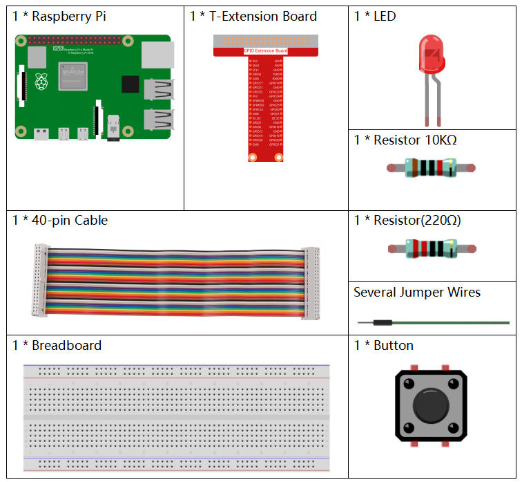
Components
Principle
Button
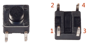
Button is a common component used to control electronic devices. It is usually used as switch to connect or break circuits. Although buttons come in a variety of sizes and shapes, the one used here is a 6mm mini-button as shown in the following pictures.
Two pins on the left are connected, and the one on the right is similar to the left, which is shown below:
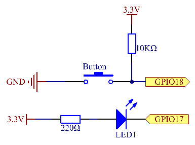
The symbol shown as below is usually used to represent a button in circuits.
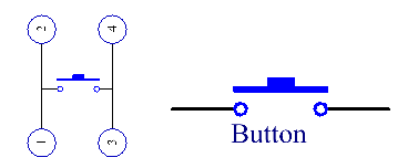
When the button is pressed, the 4 pins are connected, thus closing the circuit.
Schematic Diagram
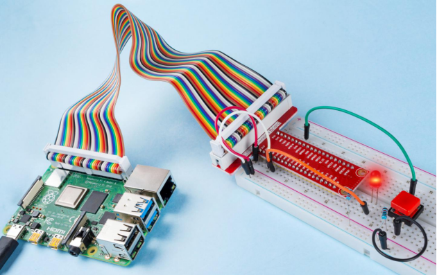
Use a normally open button as the input of Raspberry Pi, the connection is shown in the schematic diagram below. When the button is pressed, the GPIO18 will turn into low level (0V). We can detect the state of the GPIO18 through programming. That is, if the GPIO18 turns into low level, it means the button is pressed. You can run the corresponding code when the button is pressed, and then the LED will light up.
Note: The longer pin of the LED is the anode and the shorter one is the cathode.
| T-Board Name | physical | wiringPi | BCM |
| GPIO17 | Pin 11 | 0 | 17 |
| GPIO18 | Pin 12 | 1 | 18 |
Experimental Procedures
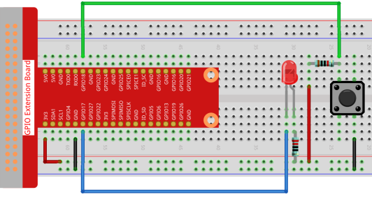
Step 1: Build the circuit.
- For C Language Users
Step 2: Open the code file.
cd /home/pi/davinci-kit-for-raspberry-pi/c/2.1.1/Note: Change directory to the path of the code in this experiment via cd.
Step 3: Compile the code.
gcc 2.1.1_Button.c -lwiringPiStep 4: Run the executable file.
sudo ./a.outAfter the code runs, press the button, the LED lights up; otherwise, turns off.
Code
#include <wiringPi.h>
#include <stdio.h>

#define LedPin      0
#define ButtonPin   1

int main(void){
    // When initialize wiring failed, print message to screen
    if(wiringPiSetup() == -1){
        printf("setup wiringPi failed !");
        return 1;
    }

    pinMode(LedPin, OUTPUT);
    pinMode(ButtonPin, INPUT);
    digitalWrite(LedPin, HIGH);

    while(1){
        // Indicate that button has pressed down
        if(digitalRead(ButtonPin) == 0){
            // Led on
            digitalWrite(LedPin, LOW);
        //  printf("...LED on\n");
        }
        else{
            // Led off
            digitalWrite(LedPin, HIGH);
        //  printf("LED off...\n");
        }
    }
    return 0;
}
Code Explanation
#define LedPin 0Pin GPIO17 in the T_Extension Board is equal to the GPIO0 in the wiringPi.
#define ButtonPin 1ButtonPin is connected to GPIO1.
pinMode(LedPin, OUTPUT);Set LedPin as output to assign value to it.
pinMode(ButtonPin, INPUT);Set ButtonPin as input to read the value of ButtonPin.
while(1){
        // Indicate that button has pressed down
        if(digitalRead(ButtonPin) == 0){
            // Led on
            digitalWrite(LedPin, LOW);
        //  printf("...LED on\n");
        }
        else{
            // Led off
            digitalWrite(LedPin, HIGH);
        //  printf("LED off...\n");
        }
    }
if (digitalRead (ButtonPin) == 0: check whether the button has been pressed. Execute digitalWrite(LedPin, LOW) when button is pressed to light up LED.
- For Python Language Users
Step 2: Open the code file.
cd /home/pi/davinci-kit-for-raspberry-pi/python Step 3: Run the code.
sudo python3 2.1.1_Button.py Now, press the button, and the LED will light up; press the button again, and the LED will go out. At the same time, the state of the LED will be printed on the screen.
Code
import RPi.GPIO as GPIO
import time
LedPin = 17  # Set GPIO17 as LED pin
BtnPin = 18  # Set GPIO18 as button pin

# Set Led status to True(OFF)
Led_status = True

# Define a setup function for some setup
def setup():
    # Set the GPIO modes to BCM Numbering
    GPIO.setmode(GPIO.BCM)
    # Set LedPin's mode to output,
    # and initial level to high (3.3v)
    GPIO.setup(LedPin, GPIO.OUT, initial=GPIO.HIGH)
    # Set BtnPin's mode to input,
    # and pull up to high (3.3V)
    GPIO.setup(BtnPin, GPIO.IN)


# Define a callback function for button callback
def swLed(ev=None):
    global Led_status
    # Switch led status(on-->off; off-->on)
    Led_status = not Led_status
    GPIO.output(LedPin, Led_status)
    if Led_status:
       print ('LED OFF...')
    else:
       print ('...LED ON')

# Define a main function for main process
def main():
# Set up a falling detect on BtnPin,
    # and callback function to swLed
    GPIO.add_event_detect(BtnPin, GPIO.FALLING, callback=swLed)
    while True:
        # Don't do anything.
        time.sleep(1)

# Define a destroy function for clean up everything after
# the script finished
def destroy():
    # Turn off LED
    GPIO.output(LedPin, GPIO.HIGH)
    # Release resource
    GPIO.cleanup()

# If run this script directly, do:
if __name__ == '__main__':
    setup()
    try:
        main()
    # When 'Ctrl+C' is pressed, the program
    # destroy() will be executed.
    except KeyboardInterrupt:
        destroy(
Code Explanation
LedPin = 17Set GPIO17 as LED pin
BtnPin = 18Set GPIO18 as button pin
GPIO.add_event_detect(BtnPin, GPIO.FALLING, callback=swLed)Set up a falling detect on BtnPin, and then when the value of BtnPin changes from a high level to a low level, it means that the button is pressed. The next step is calling the function, swled.
def swLed(ev=None):
    global Led_status
    # Switch led status(on-->off; off-->on)
    Led_status = not Led_status
    GPIO.output(LedPin, Led_status)
Define a callback function as button callback. When the button is pressed at the first time,and the condition, not Led_status is false, GPIO.output() function is called to light up the LED. As the button is pressed once again, the state of LED will be converted from false to true, thus the LED will turn off.
Phenomenon Picture