Introduction
Based on the Hall Effect, a Hall sensor is a one that varies its output voltage in response to a magnetic field. Hall sensors are used for proximity switching, positioning, speed detection, and current sensing applications.
Hall sensors can be categorized into linear (analog) Hall sensors and switch Hall sensors. A switch Hall sensor consists of voltage regulator, Hall element, differential amplifier, Schmitt trigger, and output terminal and it outputs Boolean value (0/1). A linear Hall sensor consists of Hall element, linear amplifier, and emitter follower and it outputs analog values. If a comparator is added to a linear (analog) Hall sensor, it can output both analog and digital signals.
Components
– 1 * SunFounder Uno board
– 1 * USB data cable
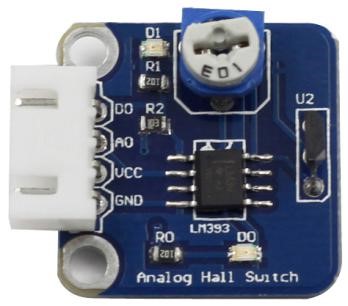
– 1 * Analog Hall sensor module
– 1 * 4-Pin anti-reverse cable
– 1 * Magnet
Experimental Principles
Hall Effect
Hall Effect is a kind of electromagnetic effect. It was discovered by Edwin Hall in 1879 when he was researching conductive mechanism about metals. The effect is seen when a conductor is passed through a uniform magnetic field. The natural electron drift of the charge carriers causes the magnetic field to apply a Lorentz force (the force exerted on a charged particle in an electromagnetic field) to these charge carriers. The result is what is seen as a charge separation, with a buildup of either positive or negative charges on the bottom or on the top of the plate.
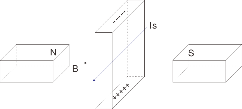
A Hall sensor is a magnetic field sensor based on it.
Electricity carried through a conductor will produce a magnetic field that varies with current, and a Hall sensor can be used to measure the current without interrupting the circuit. Typically, the sensor is integrated with a wound core or permanent magnet that surrounds the conductor to be measured.
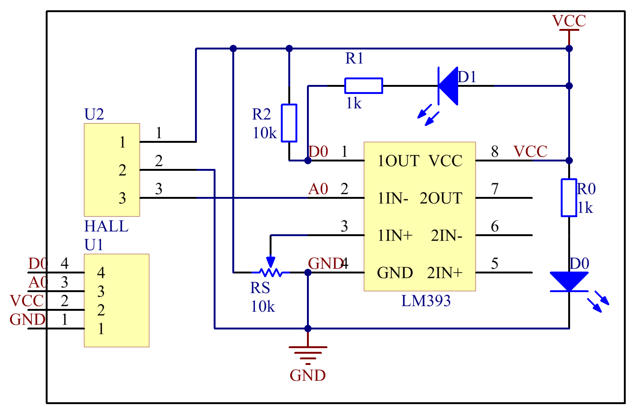
In this experiment, when the sensor approaches the magnet, the value of pin A0 will change. When the value exceeds the threshold set by the potentiometer before, D0 will output low level and the corresponding LED lights up.
The schematic diagram of the analog Hall sensor module
Experimental Procedures
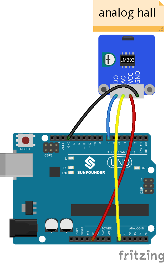
Step 1: Build the circuit
Step 2: Program (Please refer to the example code in LEARN -> Get Tutorials on our website)
Step 3: Compile
Step 4: Upload the sketch to SunFounder Uno board
Now, put a magnet close to the Hall sensor. The voltage of D0 changes from high to low, and then the LED on the sensor and that attached to pin 13 of the SunFounder Uno light up. You can see the value of A0 and D0 on Serial Monitor.
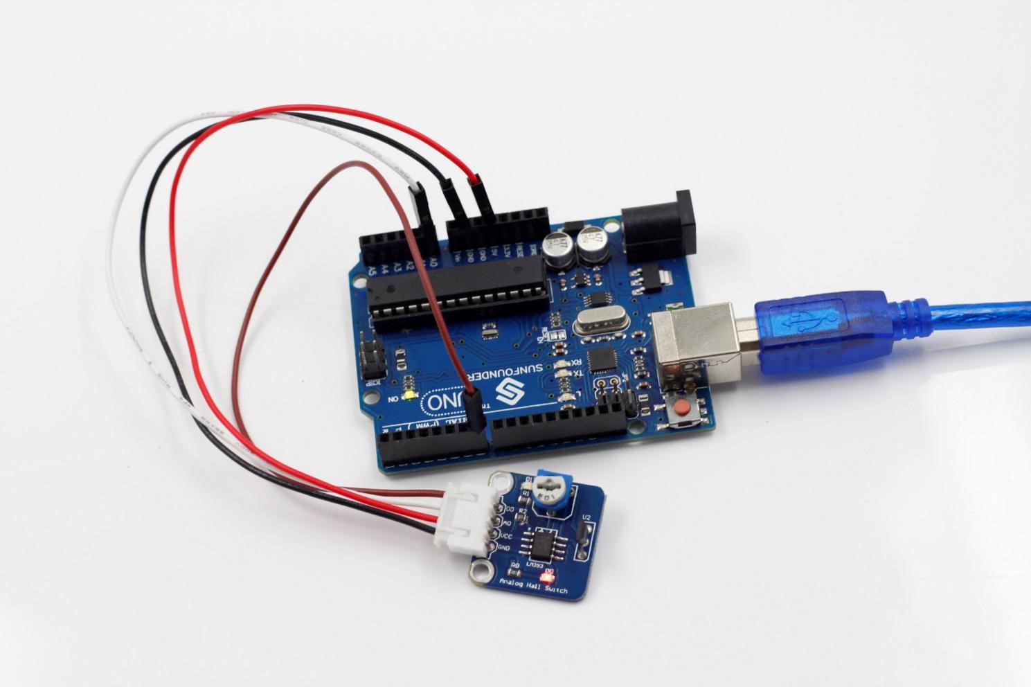
Before the experiment
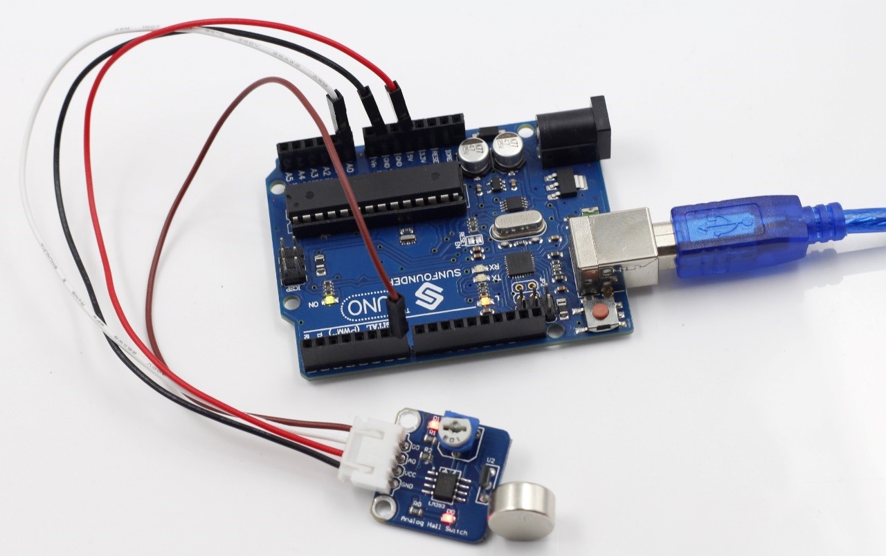
After the experiment
Code
| //Analog Hall Sensor //using an LM393 Low Power Low Offset Voltage Dual Comparator /******************************* * Analog Hall Sensor Uno R3 * A0 A0 * D0 7 * VCC 5V * GND GND *******************************/const int ledPin = 13;//the led attach to pin13 int sensorPin = A0; // select the input pin for the potentiometer int digitalPin=7; //D0 attach to pin7int sensorValue = 0;// variable to store the value coming from A0 boolean digitalValue=0;// variable to store the value coming from pin7void setup() { pinMode(digitalPin,INPUT);//set the state of D0 as INPUT pinMode(ledPin,OUTPUT);//set the state of pin13 as OUTPUT Serial.begin(9600); // initialize serial communications at 9600 bps}void loop() { sensorValue = analogRead(sensorPin); //read the value of A0 digitalValue=digitalRead(digitalPin); //read the value of D0 Serial.print(“Sensor Value “); // print label to serial monitor Serial.println(sensorValue); //print the value of A0 Serial.print(“Digital Value “); // print label to serial monitor Serial.println(digitalValue); //print the value of D0 in the serial if( digitalValue==HIGH )//if the value of D0 is HIGH { digitalWrite(ledPin,LOW);//turn off the led } if( digitalValue==LOW)//else { digitalWrite(ledPin,HIGH);//turn on the led } delay(1000);//delay 200ms } |