Introduction
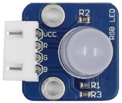
RGB LED modules can emit various colors of light. Three LEDs of red, green, and blue are packaged into a transparent or semitransparent plastic shell with four pins led out. The three primary colors of red, green, and blue can be mixed and compose all kinds of colors by brightness, so you can make an RGB LED emit colorful light by controlling the circuit.
Components
– 1 * Raspberry Pi
– 1 * Breadboard
– 1 * Network cable (or USB wireless network adapter)
– 1 * RGB LED module
– 1 * 4-Pin anti-reverse cable
Experimental Principle
In this experiment, we will use PWM technology to control the brightness of RGB.
Pulse Width Modulation, or PWM, is a technique for getting analog results with digital means. Digital control is used to create a square wave, a signal switched between on and off. This on-off pattern can simulate voltages in between full on (5 Volts) and off (0 Volts) by changing the portion of the time the signal spends on versus the time that the signal spends off. The duration of “on time” is called the pulse width. To get varying analog values, you change, or modulate, that pulse width. If you repeat this on-off pattern fast enough with an LED for example, the result is as if the signal is a steady voltage between 0 and 5v controlling the brightness of the LED.

We can see from the top oscillogram that the amplitude of DC voltage output is 5V. However, the actual voltage output is only 3.75V through PWM, for the high level only takes up 75% of the total voltage within a period.
Here are the three basic parameters of PWM:
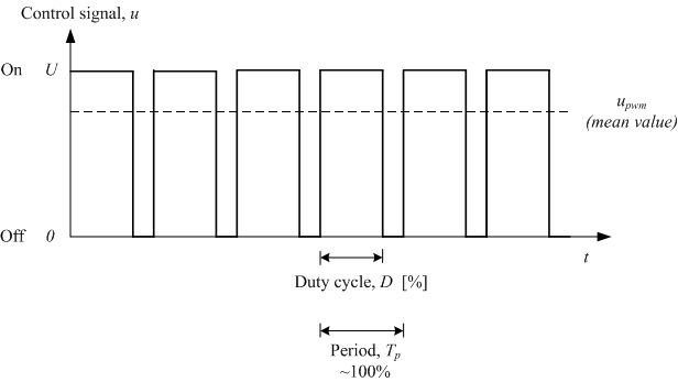
1. The term duty cycle describes the proportion of “on” time to the regular interval or “period” of time
2. Period describes the reciprocal of pulses in one second.
3. The voltage amplitude here is 0-5V.
Input a value between 0 and 255 to the three pins of the RGB LED to make it display different colors.
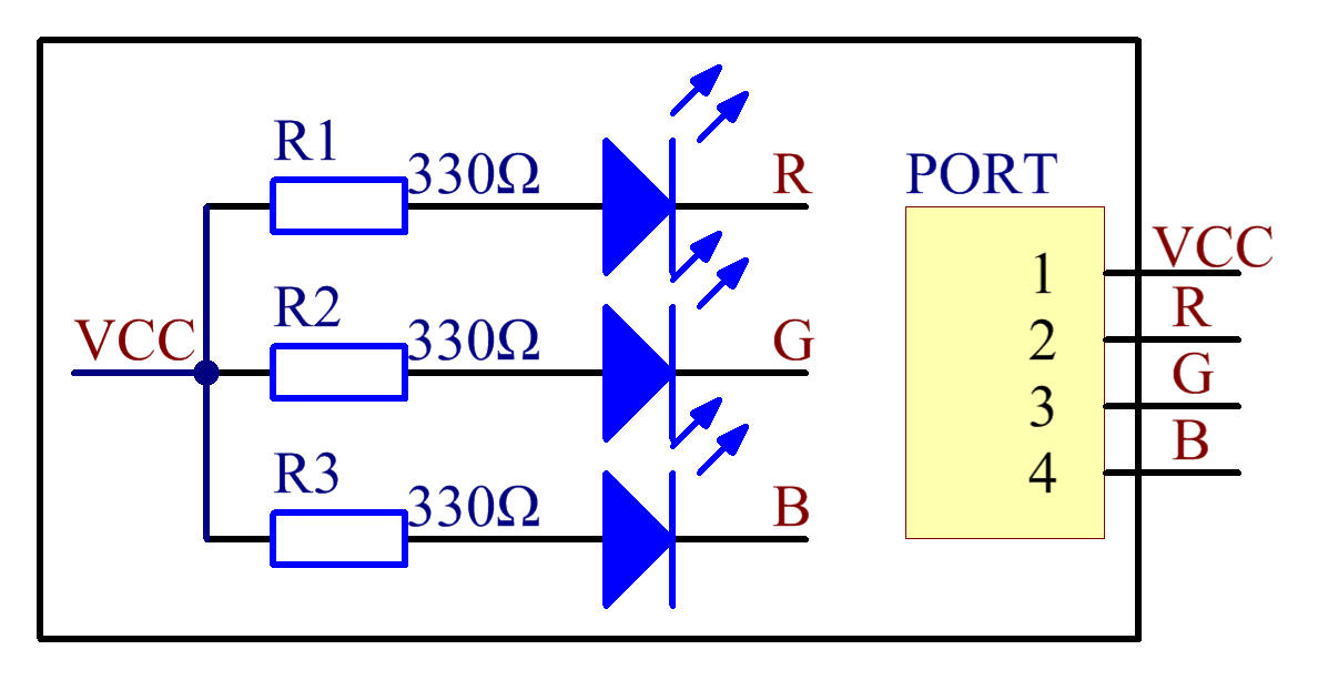
RGB LEDs can be categorized into common anode LED and common cathode LED. In this experiment, a common cathode RGB LED is used.
The schematic diagram:
Experimental Procedures
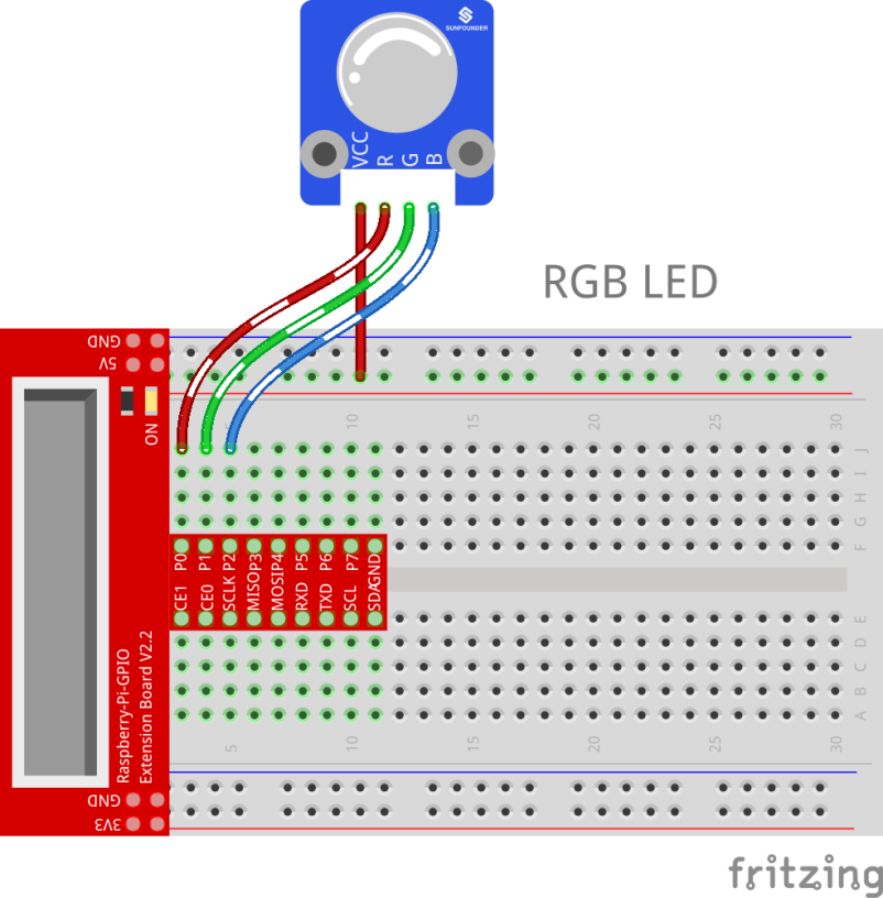
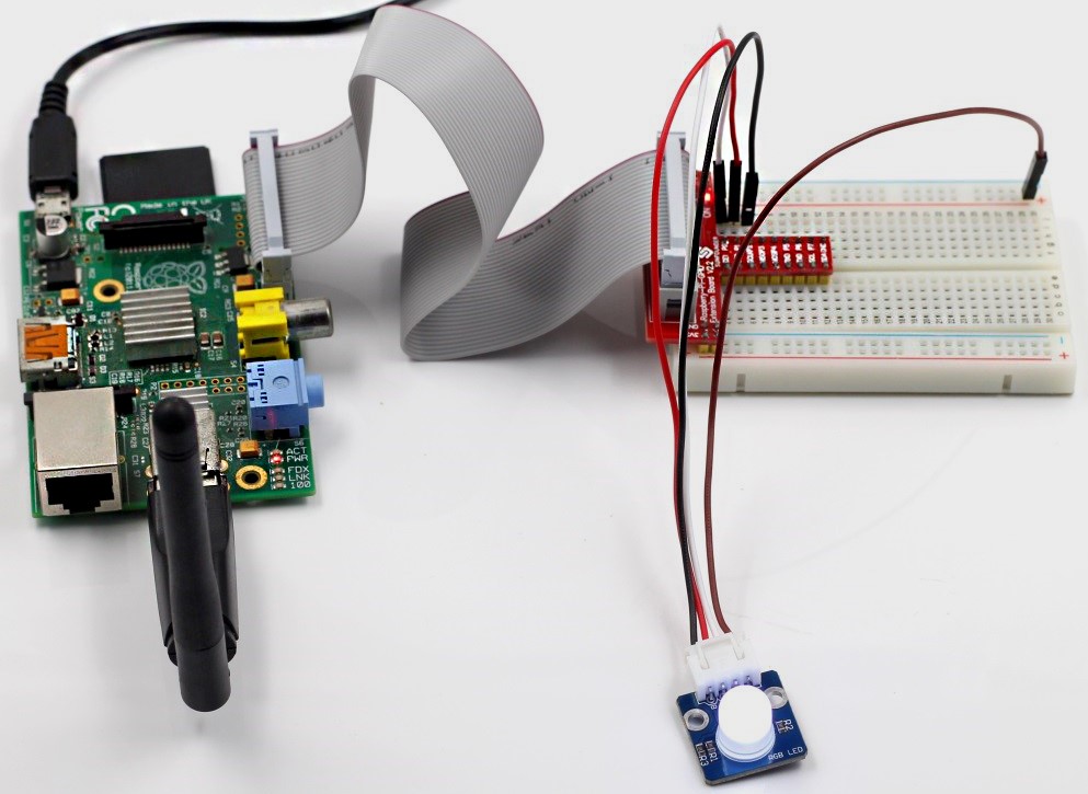
Step 1: Build the circuit
| Raspberry Pi | RGB LED Module |
| 5V | VCC |
| GPIO0 | R |
| GPIO1 | G |
| GPIO2 | B |
For C language users:
Step 2: Change directory
cd /home/pi/SunFounder_SensorKit_for_RPi2/C/02_rgb_led/
Step 3: Compile
gcc rgb_led.c –lwiringPi
Step 4: Run
sudo ./a.out
For Python users:
Step 2: Change directory
cd /home/pi/SunFounder_SensorKit_for_RPi2/Python/
Step 3: Run
sudo python 02_rgb_led.py
Now you can see the RGB LED light up, and flash different colors in turn.
C Code
#include <wiringPi.h>
#include <softPwm.h>
#include <stdio.h>

#define uchar unsigned char

#define LedPinRed    0
#define LedPinGreen  1
#define LedPinBlue   2

void ledInit(void)
{
	softPwmCreate(LedPinRed,  0, 100);
	softPwmCreate(LedPinGreen,0, 100);
	softPwmCreate(LedPinBlue, 0, 100);
}

void ledColorSet(uchar r_val, uchar g_val, uchar b_val)
{
	softPwmWrite(LedPinRed,   r_val);
	softPwmWrite(LedPinGreen, g_val);
	softPwmWrite(LedPinBlue,  b_val);
}

int main(void)
{
	int i;

	if(wiringPiSetup() == -1){ //when initialize wiring failed, print message to screen
		printf("setup wiringPi failed !");
		return 1;
	}
	//printf("linker LedPin : GPIO %d(wiringPi pin)\n",LedPin); //when initialize wiring successfully,print message to screen

	ledInit();

	while(1){
		ledColorSet(0xff,0x00,0x00);   //red
		delay(500);
		ledColorSet(0x00,0xff,0x00);   //green
		delay(500);
		ledColorSet(0x00,0x00,0xff);   //blue
		delay(500);

		ledColorSet(0xff,0xff,0x00);   //yellow
		delay(500);
		ledColorSet(0xff,0x00,0xff);   //pick
		delay(500);
		ledColorSet(0xc0,0xff,0x3e);
		delay(500);

		ledColorSet(0x94,0x00,0xd3);
		delay(500);
		ledColorSet(0x76,0xee,0x00);
		delay(500);
		ledColorSet(0x00,0xc5,0xcd);
		delay(500);

	}

	return 0;
}
Python Code
#!/usr/bin/env python
import RPi.GPIO as GPIO
import time

colors = [0xFF0000, 0x00FF00, 0x0000FF, 0xFFFF00, 0xFF00FF, 0x00FFFF]
R = 11
G = 12
B = 13

def setup(Rpin, Gpin, Bpin):
	global pins
	global p_R, p_G, p_B
	pins = {'pin_R': Rpin, 'pin_G': Gpin, 'pin_B': Bpin}
	GPIO.setmode(GPIO.BOARD)       # Numbers GPIOs by physical location
	for i in pins:
		GPIO.setup(pins[i], GPIO.OUT)   # Set pins' mode is output
		GPIO.output(pins[i], GPIO.HIGH) # Set pins to high(+3.3V) to off led

	p_R = GPIO.PWM(pins['pin_R'], 2000)  # set Frequece to 2KHz
	p_G = GPIO.PWM(pins['pin_G'], 1999)
	p_B = GPIO.PWM(pins['pin_B'], 5000)

	p_R.start(100)      # Initial duty Cycle = 0(leds off)
	p_G.start(100)
	p_B.start(100)

def map(x, in_min, in_max, out_min, out_max):
	return (x - in_min) * (out_max - out_min) / (in_max - in_min) + out_min

def off():
	for i in pins:
		GPIO.output(pins[i], GPIO.HIGH)    # Turn off all leds

def setColor(col):   # For example : col = 0x112233
	R_val = (col & 0xff0000) >> 16
	G_val = (col & 0x00ff00) >> 8
	B_val = (col & 0x0000ff) >> 0

	R_val = map(R_val, 0, 255, 0, 100)
	G_val = map(G_val, 0, 255, 0, 100)
	B_val = map(B_val, 0, 255, 0, 100)

	p_R.ChangeDutyCycle(100-R_val)     # Change duty cycle
	p_G.ChangeDutyCycle(100-G_val)
	p_B.ChangeDutyCycle(100-B_val)

def loop():
	while True:
		for col in colors:
			setColor(col)
			time.sleep(1)

def destroy():
	p_R.stop()
	p_G.stop()
	p_B.stop()
	off()
	GPIO.cleanup()

if __name__ == "__main__":
	try:
		setup(R, G, B)
		loop()
	except KeyboardInterrupt:
		destroy()