Introduction
In this lesson, we will continue to make amusing experiment – simulate a traffic light. The colored lights of a traffic light are typically red for stop, green for go, and yellow for proceed with caution. We’ll use LEDs for the indicators. Let’s get started!
Components
– 1 * SunFounder Uno board
– 1 * Breadboard
– 6 * LED (2 red, 2 yellow, and 2 green)
– 7 * Resistor (220Ω)
– 1 * 7-segment display
– 1* 74HC595
– 1 * USB cable
– Jumper wires
Principle
The schematic diagram
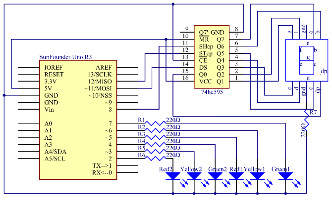
In this experiment, we use a 7-segment display to count down and set two groups of traffic lights to represent two directions, let’s say, north-south (NS) and east-west (EW), as shown in the following figure in Procedures. First, count down from 9s, and the red light in the NS and the green one in the EW light up. As time goes by, after 9s, the 7-segment begins to count down from 3s, the green LED in the EW goes out when the yellow lights up, the NS red light keeps on. 3s later, the 7-segment counts down from 9s again. At the same time, the red light in the EW and the green in the NS light up. After 9s, the 7-segment counts down from 3s again, when the yellow light in the NS lights up and the red in the EW keeps on. This process simulates the working of traffic lights.
Note: The 7-segment display is controlled by 74HC595 as shown in Lesson 11 previously. There is no current limiting resistor between the pins of 7-segment display and Q0-Q7 but one to the GND. It can also protect the 7-segment display when making a simplified circuit.
Experimental Procedures
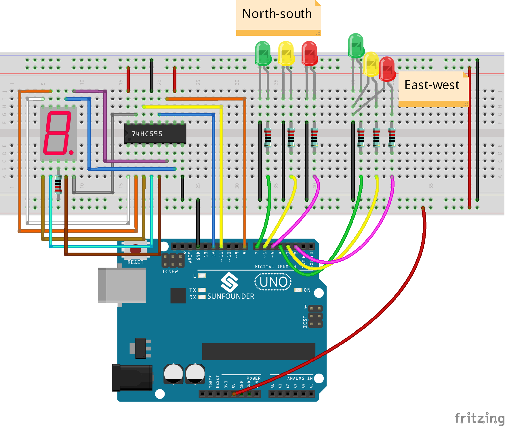
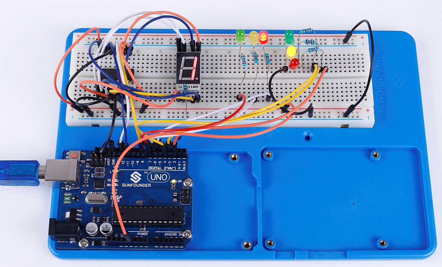
Step 1: Build the circuit
Step 2: Open the code file
Step 3: Select correct Board and Port
Step 4: Upload the sketch to the SunFounder Uno board
You can see what is similar to the traffic light now. First, the 7-segment display counts down from 9s, and the red light in the NS and the green one in the EW light up. Then it counts down from 3, and the green LED in the EW goes out when the yellow lights up, with the NS red light still on. 3s later, the 7-segment counts down from 9s again. Meanwhile, the red light in the EW and the green in the NS light up. After 9s, it counts down from 3s, when the yellow light in the NS lights up and the red in the EW keeps on.
Code
| //Traffic Light //You will see the red LED light up first, then the red LED and yellow LED, followed by the green LED, and finally the yellow LED again. //Email:support@sunfounder.com //Website:www.sunfounder.com //2015.5.7 const int red1Pin= 5; //red1 led attach to const int yellow1Pin =6 ; //yellow1 led attach to const int green1Pin= 7; //green1 led attach to const int red2Pin= 2; //red2 led attach to const int yellow2Pin =3 ; //yellow2 led attach to const int green2Pin= 4; //green2 led attach to const int STcp = 12;//Pin connected to ST_CP of 74HC595 const int SHcp = 8;//Pin connected to SH_CP of 74HC595 const int DS = 11; //Pin connected to DS of 74HC595 //display 1,2,3,4,5,6,7,8,9 int datArray[16] = { 96, 218, 242, 102, 182, 190, 224, 254, 246}; void setup() { pinMode(red1Pin, OUTPUT); //set the redPin as an output pinMode(yellow1Pin, OUTPUT); //set the yellowPin as an output pinMode(green1Pin, OUTPUT); //set the greenPin as an output pinMode(red2Pin, OUTPUT); //set the redPin as an output pinMode(yellow2Pin, OUTPUT); //set the yellowPin as an output pinMode(green2Pin, OUTPUT); //set the greenPin as an output //set pins to output pinMode(STcp,OUTPUT); pinMode(SHcp,OUTPUT); pinMode(DS,OUTPUT); Serial.begin(9600); // start serial port at 9600 bps: } void loop() { State1(); State2(); } void State1() { digitalWrite(red1Pin,HIGH); //turn on a red led for(int num = 8; num >=0; num–) //display 9-1 and turn on a green led { digitalWrite(green2Pin,HIGH); digitalWrite(STcp,LOW); //ground ST_CP and hold low for transmitting shiftOut(DS,SHcp,MSBFIRST,datArray[num]); digitalWrite(STcp,HIGH); //pull the ST_CPST_CP to save the data delay(1000); //wait for a second } digitalWrite(green2Pin,LOW); //turn off the green led for(int num = 2 ;num >=0; num–) //diaplay 3 to 1 and turn on the yellow led { digitalWrite(yellow2Pin,HIGH); digitalWrite(STcp,LOW); //ground ST_CP and hold low for transmitting shiftOut(DS,SHcp,MSBFIRST,datArray[num]); digitalWrite(STcp,HIGH); //pull the ST_CPST_CP to save the data delay(1000); //wait for a second } digitalWrite(yellow2Pin,LOW); //turn off the yellow led digitalWrite(red1Pin,LOW); //the red led finally turn off } void State2() { digitalWrite(red2Pin,HIGH); for(int num = 8; num >=0; num–) { digitalWrite(green1Pin,HIGH); digitalWrite(STcp,LOW); //ground ST_CP and hold low for as long as you are transmitting shiftOut(DS,SHcp,MSBFIRST,datArray[num]); digitalWrite(STcp,HIGH); //pull the ST_CPST_CP to save the data delay(1000); //wait for a second } digitalWrite(green1Pin,LOW); for(int num = 2 ;num >=0; num–) { digitalWrite(yellow1Pin,HIGH); digitalWrite(STcp,LOW); //ground ST_CP and hold low for as long as you are transmitting shiftOut(DS,SHcp,MSBFIRST,datArray[num]); digitalWrite(STcp,HIGH); //pull the ST_CPST_CP to save the data delay(1000); //wait for a second } digitalWrite(yellow1Pin,LOW); digitalWrite(red2Pin,LOW); } |