Introduction
There are two kinds of microphone sensor in this kit: microphone sensor and high-sensitive voice sensor (as shown below). The only difference between them is sensitivity. In this experiment, we will take the microphone sensor for example. You may try to apply the other sensor based on what you’ve got during the process.
Both sensors have two outputs:
AO: analog output, to output voltage signals from microphone in a real-time manner
DO: When the sound intensity reaches a certain threshold, the sensor outputs high or low level (you can adjust the threshold by the potentiometer)
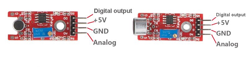
Microphone Sensor High-sensitive Voice Sensor
Components
– 1 * Raspberry Pi
– 1 * Breadboard
– 1 * ADC0832
– 1 * Network cable (or USB wireless network adapter)
– 1 * Microphone sensor module
– 1 * High-Sensitive voice sensor module
– Several jumper wires
Experimental Principle
Microphone can convert audio signal into electrical signal (analog quantity), then convert analog quantity into digital value by ADC and transfer it to MCU to process.
The schematic diagram:
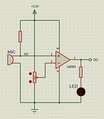
LM393 is a voltage comparator. When the voltage of the in-phase terminal (pin 3) is higher than that of the inverting terminal (pin 2), the output terminal (pin 1) will output high. Otherwise, it outputs low. First, adjust the potentiometer to make the voltage for pin 2 of LM393 less than 3.3V. When there is no voice input, the resistance of the microphone is very large. The voltage for pin 3 of LM393 is close to power supply voltage (3.3V), pin 1 outputs high and the LED is on; when there is voice input, the resistance of the microphone decreases, pin 1 outputs low and the LED is off. And connect pin 1 to IO of the SunFounder Uno board to detect sounds by programming.
ADC0832 is an 8-bit two-channel A/D conversion chip. Connect the output terminal (AO) to CH0 of ADC0832 so as to make real-time detection of the strength of voice signals.
Experimental Procedures
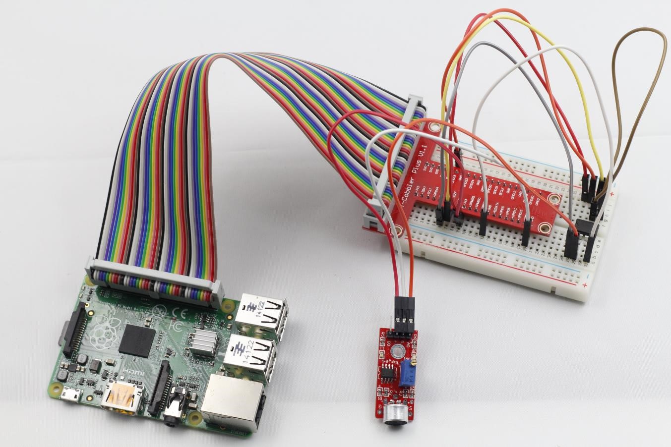
Step 1: Build the circuit
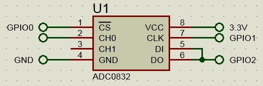
Connect pin DO on the microphone sensor module to pin GPIO3 on Raspberry Pi; pin AO of the module to CH0 of the ADC0832.
Step 2: Edit code and save (see path/Rpi_SensorKit_code/23_microPhoneSensor/microPhone.c)
Step 3: Compile
gcc microPhone.c -lwiringPi
Step 4: Run
./a.out
Now, speak or blow to the microphone, and you will see “voice in” and “Current analog value: ***” printed on the screen.
microPhone.c
#include <wiringPi.h>
#include <stdio.h>
#include <string.h>
#include <errno.h>
#include <stdlib.h>

#define     ADC_CS    0
#define     ADC_CLK   1
#define     ADC_DIO   2

#define  MIC_DO_Pin   3

typedef unsigned char uchar;
typedef unsigned int uint;


uchar get_ADC_Result(void)
{
	uchar i;
	uchar dat1=0, dat2=0;

	digitalWrite(ADC_CS, 0);
	digitalWrite(ADC_CLK,0);
	digitalWrite(ADC_DIO,1);	delayMicroseconds(2);
	digitalWrite(ADC_CLK,1);	delayMicroseconds(2);

	digitalWrite(ADC_CLK,0);
	digitalWrite(ADC_DIO,1);    delayMicroseconds(2);
	digitalWrite(ADC_CLK,1);	delayMicroseconds(2);

	digitalWrite(ADC_CLK,0);
	digitalWrite(ADC_DIO,0);	delayMicroseconds(2);
	digitalWrite(ADC_CLK,1);
	digitalWrite(ADC_DIO,1);    delayMicroseconds(2);
	digitalWrite(ADC_CLK,0);
	digitalWrite(ADC_DIO,1);    delayMicroseconds(2);

	for(i=0;i<8;i++)
	{
		digitalWrite(ADC_CLK,1);	delayMicroseconds(2);
		digitalWrite(ADC_CLK,0);    delayMicroseconds(2);

		pinMode(ADC_DIO, INPUT);
		dat1=dat1<<1 | digitalRead(ADC_DIO);
	}

	for(i=0;i<8;i++)
	{
		dat2 = dat2 | ((uchar)(digitalRead(ADC_DIO))<<i);
		digitalWrite(ADC_CLK,1); 	delayMicroseconds(2);
		digitalWrite(ADC_CLK,0);    delayMicroseconds(2);
	}

	digitalWrite(ADC_CS,1);

	return(dat1==dat2) ? dat1 : 0;
}

void micISR(void)
{
	uchar analogVal;

	printf("voice in \n");

	pinMode(ADC_DIO, OUTPUT);

	analogVal = get_ADC_Result();
	printf("Current analog : %d\n", analogVal);
}

int main(void)
{

	if(wiringPiSetup() == -1){ //when initialize wiring failed,print messageto screen
		printf("setup wiringPi failed !");
		return 1;
	}

	if(wiringPiISR(MIC_DO_Pin, INT_EDGE_RISING, &micISR) < 0){
		fprintf(stderr, "Unable to init ISR\n",strerror(errno));
		return 1;
	}

	pinMode(ADC_CS,  OUTPUT);
	pinMode(ADC_CLK, OUTPUT);

	printf("Please speaking...\n");

	while(1){

	}

	return 0;
}
Python Code
#!/usr/bin/env python
import RPi.GPIO as GPIO
import ADC0832
import time

MIC_DO_PIN = 15

def init():
	GPIO.setmode(GPIO.BOARD)
	GPIO.setup(MIC_DO_PIN, GPIO.IN, pull_up_down=GPIO.PUD_UP)
	ADC0832.setup()

def micISR(ev=None):
	print "voice in..."
	analogVal = ADC0832.getResult()
	print 'res = %d' % res

def loop():
	GPIO.add_event_detect(MIC_DO_PIN, GPIO.FALLING, callback=micISR)
	while True:
		pass

if __name__ == '__main__':
	init()
	try:
		loop()
	except KeyboardInterrupt:
		ADC0832.destroy()
		print 'The end !'