Introduction
There are two kinds of microphone sensor in this kit: microphone sensor and high-sensitive voice sensor (as shown below). The only difference between them is sensitivity. In this experiment, we will take the microphone sensor for example. You may try to apply the other sensor based on what you’ve got during the process.
Both sensors have two outputs:
AO: analog output, to output voltage signals from microphone in a real-time manner
DO: When sound intensity reaches a certain threshold, the sensor outputs high or low level (you can adjust the threshold by potentiometer)

Microphone Sensor High-sensitive Voice Sensor
Components
– 1 * SunFounder Uno board
– 1 * Breadboard
– 1 * USB data cable
– 1 * Microphone sensor module
– Several jumper wires
Experimental Principle
Microphone can convert audio signal into electrical signal (analog quantity), then convert analog quantity into digital value by ADC and transfer it to MCU to process.
The schematic diagram:

LM393 is a voltage comparator. When the voltage of the in-phase terminal (pin 3) is higher than that of the inverting terminal (pin 2), the output terminal (pin 1) will output high. Otherwise, it outputs low. First, adjust the potentiometer to make the voltage for pin 2 of LM393 less than 5V. When there is no voice input, the resistance of the microphone is very large. The voltage for pin 3 of LM393 is close to power supply voltage (5V), pin 1 outputs high and the LED is on; when there is voice input, the resistance of the microphone decreases, pin 1 outputs low and the LED is off. And connect pin 1 to IO of the SunFounder Uno board to detect sounds by programming.
Experimental Procedures
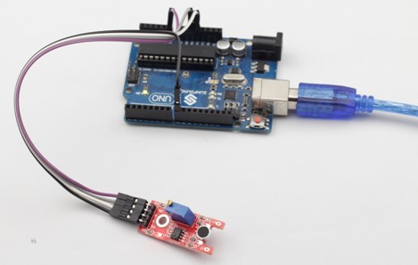
Step 1: Build the circuit
Microphone Sensor Module SunFounder Uno
AO —————————————- A0
G —————————————– GND
+ —————————————– 5V
DO —————————————-D8
Step 2: Program (Please refer to the example code in LEARN -> Get Tutorial on our website)
Step 3: Compile
Step 4: Upload the sketch to SunFounder Uno
Now, speak near or blow into the microphone, and you can see the LED attached to pin 13 on the SunFounder Uno board brighten.
Code for Microphone
| const int ledPin = 13; //the led attach to const int soundPin = A0;void setup() { pinMode(ledPin,OUTPUT); Serial.begin(9600); }void loop() { int value = analogRead(soundPin); Serial.println(value); if(value > 30) { digitalWrite(ledPin,HIGH); delay(200); } else { digitalWrite(ledPin,LOW); } } |
Code for High-sensitive Voice Sensor
| const int ledPin = 13; const int soundPin = A0;void setup() { pinMode(ledPin,OUTPUT); Serial.begin(9600); }void loop() { int value = analogRead(soundPin); Serial.println(value); if(value > 25) { digitalWrite(ledPin,HIGH); delay(20000); } else { digitalWrite(ledPin,LOW); } } |