Introduction
In this project, we will use LED lights of three colors to realize the change of traffic lights and a four-digit 7-segment display will be used to display the timing of each traffic state.
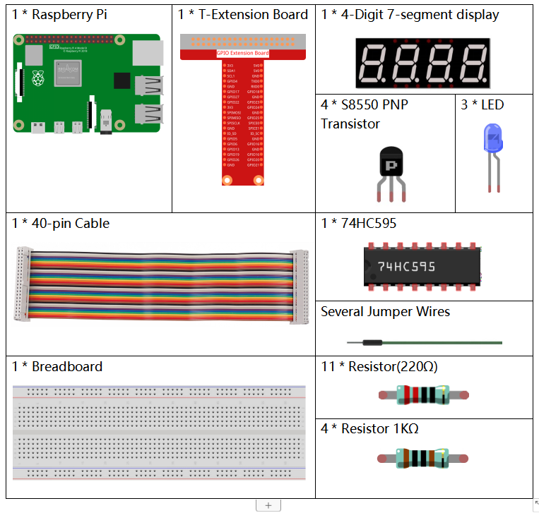
Components
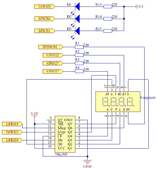
Schematic Diagram
| T-Board Name | physical | wiringPi | BCM |
| GPIO17 | Pin 11 | 0 | 17 |
| GPIO27 | Pin 13 | 2 | 27 |
| GPIO22 | Pin 15 | 3 | 22 |
| SPIMOSI | Pin 19 | 12 | 10 |
| GPIO18 | Pin 12 | 1 | 18 |
| GPIO23 | Pin 16 | 4 | 23 |
| GPIO24 | Pin 18 | 5 | 24 |
| GPIO25 | Pin 22 | 6 | 25 |
| SPICE0 | Pin 24 | 10 | 8 |
| SPICE1 | Pin 26 | 11 | 7 |
Experimental Procedures
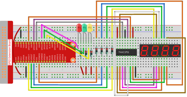
Step 1: Build the circuit.
- For C Language Users
Step 2: Change directory.
cd /home/pi/davinci-kit-for-raspberry-pi/c/3.1.7/Step 3: Compile.
gcc 3.1.7_TrafficLight.c -lwiringPiStep 4: Run.
sudo ./a.outAs the code runs, LEDs will simulate the color changing of traffic lights. Firstly, the red LED lights up for 60s, then the green LED lights up for 30s; next, the yellow LED lights up for 5s. After that, the red LED lights up for 60s once again. In this way, this series of actions will be executed repeatedly.
Code Explanation
#define     SDI     5
#define     RCLK    4
#define     SRCLK    1

const int placePin[] = {12, 3, 2, 0};
unsigned char number[] = {0xc0, 0xf9, 0xa4, 0xb0, 0x99, 0x92, 0x82, 0xf8, 0x80, 0x90};

void pickDigit(int digit);
void hc595_shift(int8_t data);
void clearDisplay();
void display();
These codes are used to realize the function of number display of 4-Digit 7-Segment Displays. Refer to chapter 1.1.5 of the document for more details. Here, we use the codes to display countdown of traffic light time.
const int ledPin[]={6,10,11};

int colorState = 0;

void lightup()
{
    for(int i=0;i<3;i++){
        digitalWrite(ledPin[i],HIGH);
    }
    digitalWrite(ledPin[colorState],LOW);
}
The codes are used to switch the LED on and off.
int greenLight = 30;
int yellowLight = 5;
int redLight = 60;
int colorState = 0;
char *lightColor[]={"Red","Green","Yellow"};
int counter = 60;

void timer(int  timer1){       //Timer function
    if(timer1 == SIGALRM){
        counter --;
        alarm(1);
        if(counter == 0){
            if(colorState == 0) counter = greenLight;
            if(colorState == 1) counter = yellowLight;
            if(colorState == 2) counter = redLight;
            colorState = (colorState+1)%3;
        }
        printf("counter : %d \t light color: %s \n",counter,lightColor[colorState]);
    }
}
The codes are used to switch the timer on and off. Refer to chapter 1.1.5 for more details. Here, when the timer returns to zero, colorState will be switched so as to switch LED, and the timer will be assigned to a new value.
void loop()
{
    while(1){
    display();
    lightup();
    }
}

int main(void)
{
    //…
    signal(SIGALRM,timer);
    alarm(1);
    loop();
    return 0;
}
The timer is started in the main() function. In loop() function, use while(1) loop and call the functions of 4-Digit 7-Segment and LED.
- For Python Language Users
Step 2: Change directory.
cd /home/pi/davinci-kit-for-raspberry-pi/python/Step 3: Run.
sudo python3 3.1.7_TrafficLight.pyAs the code runs, LEDs will simulate the color changing of traffic lights. Firstly, the red LED lights up for 60s, then the green LED lights up for 30s; next, the yellow LED lights up for 5s. After that, the red LED lights up for 60s once again. In this way, this series of actions will be executed repeatedly. Meanwhile, the 4-digit 7-segment display displays the countdown time continuously.
Code Explanation
SDI   = 24      #serial data input(DS)
RCLK  = 23     #memory clock input(STCP)
SRCLK = 18      #shift register clock input(SHCP)
number = (0xc0,0xf9,0xa4,0xb0,0x99,0x92,0x82,0xf8,0x80,0x90)
placePin = (17,27,22,10)

def clearDisplay():
def hc595_shift(data):
def pickDigit(digit):
def display():
These codes are used to realize the function of number display of 4-Digit 7-Segment. Refer to chapter 1.1.5 of the document for more details. Here, we use the codes to display countdown of traffic light time.
ledPin =(22,24,26)
colorState=0

def lightup():
    global colorState
    for i in range(0,3):
        GPIO.output(ledPin[i], GPIO.HIGH)
    GPIO.output(ledPin[colorState], GPIO.LOW)
The codes are used to switch the LED on and off.
greenLight = 30
yellowLight = 5
redLight = 60
lightColor=("Red","Green","Yellow")

colorState=0
counter = 60
timer1 = 0

def timer():        #timer function
    global counter
    global colorState
    global timer1
    timer1 = threading.Timer(1.0,timer)
    timer1.start()
    counter-=1
    if (counter is 0):
        if(colorState is 0):
            counter= greenLight
        if(colorState is 1):
            counter=yellowLight
        if (colorState is 2):
            counter=redLight
        colorState=(colorState+1)%3
    print ("counter : %d    color: %s "%(counter,lightColor[colorState]))
The codes are used to switch the timer on and off. Refer to chapter 1.1.5 for more details. Here, when the timer returns to zero, colorState will be switched so as to switch LED, and the timer will be assigned to a new value.
def setup():
    # ...
    global timer1
    timer1 = threading.Timer(1.0,timer)
    timer1.start()

def loop():
    while True:
        display()
        lightup()

def destroy():   # When "Ctrl+C" is pressed, the function is executed.
    global timer1
    GPIO.cleanup()
    timer1.cancel()      #cancel the timer

if __name__ == '__main__': # Program starting from here
    setup()
    try:
        loop()
    except KeyboardInterrupt:
        destroy()
In setup() function, start the timer. In loop() function, a while True is used: call the relative functions of 4-Digit 7-Segment and LED circularly.
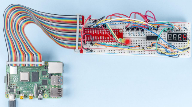
Phenomenon Picture